
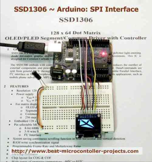
This section is all about using an SSD1306 OLED (Organic LED) display that's 128 pixels wide by 64 pixels high. This is a very small display (0.96""), so you should use larger font sizes and graphics to display useful information.
In the examples below you can test out the different libraries "Adafruit SSD1306" and U8G2. While the Adafruit is specific to a few versions of the hardware the U8G2 library (Universal graphics 8 bit library) can be used with many, many different display modules.
In a way this is good since you can use the same drawing functions but you also have more constructor options to look at, and selecting the right one may not be so easy.
I found on my first attempt that the U8G2 library would not operate the display using what I thought were the correct initialisation settings so I gave up with that and tried the Adafruit library which worked 1st time (There was a slight problem with line skipping - see the solution below - that was not reliably addressed on the web).
In fact the Adafruit library sits on top of a graphics library (Adafruit GFX) so you are really using the same drawing functions and only changing the top code for the hardware.
The u8g2 library does work but there are different ways of using the display so you not only have to use the correct constructor for your specific display, but you also have to use the correct number of pins in that constructor (you may or may not have a reset line!).
A further complication is that there are several different screen buffer modes (these are also selected by the constructor) - and for these screen buffer modes different functions are required to operate the display and these functions do not mix.
The examples bellow use the correct constructor and buffer drive code. It sounds complicated but once understood, you can optimise the display and buffering for your system.
An option within the U8G2 library is for direct output of screen data which means zero buffering - See the sections on u8x8 library. This means you get all your RAM back with text output but no graphics - which can be a useful option for severely constrained designs.
SSD1306 Datasheet
Download the datasheet here.
SSD1306 Specification
ParameterValue
| Voltage Supply (Vcc) | 6V ~ 15V |
| Digital Supply voltage (Vdd i/o) | 1.65V ~ 3V3 |
| Vbat | 2V2 ~ 4V2 |
| Abs.Max VCC | 0 ~ 16V |
| Abs.Max VDD | -0.3V ~ 4V |
| Abs.Max VBAT | -0.3 ~ 5V |
| Interface | I2C / SPI [1], uC [2] |
| I2C Address (depends on ALT ADDR) | 0x1D, 0x53 |
| Interface Speed | 1/100ns = 10MHz |
| Resolution | 128x64 bits |
| Current (typ,max) | 0.9mA, 1.5mA |
| Max current sink | 30mA |
| Operating temperature | -40°C ~ 85°C |
[1] - 3 and 4 wire SPI.
[2] - Parallel interfaces 8080 and 6800.
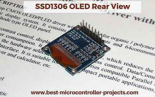
Rear view detail of OLED
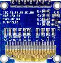
As you can see from the silkscreen instructions you can choose the operating mode from:
- IIC (I2C)
- 4SPI
- 3SPI
Note: 4SPI means you want to read back from the module and SPI means you want to just chuck data at the module. However the data sheet notes that:
"Under serial mode, only write operations are allowed."
The MISO output is therefore only to allow daisy chaining SPI modules.
The unit I have is configured with resistors R4 and R3 so that means using the 4PSI mode (you can ignore the output signal MISO anyway in this case since there are no other SPI chips used in the examples).
SSD1306 Pinout Connections
The SSD1306 is capable of working in either 4 wire SPI mode, 3wire SPI mode or I2C mode. This breakout board lets you change the function by moving resistors around (de-solder and re-solder).
The SPI is the fastest serial mode (there is a parallel mode not accessible with these breakout boards). Check the back for the resistors positions solder on the board - these set the mode in use. The examples below use 4 wire SPI interface.
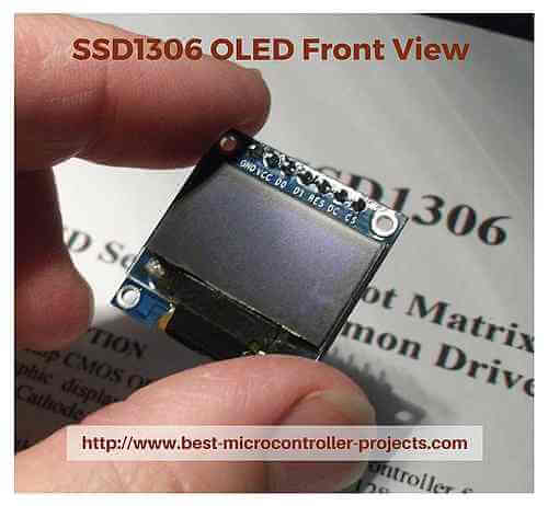
| GND | Ground (0V) | Ground (0V) | Ground (0V) | GND | GND |
| Vcc | Power Supply | Power Supply | Power Supply | 5V | 5V |
| D0 | Clock into display | SCK | SCL | 13 | D13 |
| D1 | Data into display | MOSI | SDA | 11 | D11 |
| RES | Reset | 10 | D10 | ||
| DC | Data/Command | 9 | D9 | ||
| CS | Chip Select | CS | 8 | D8 |
Note: Pins 13 (SCK) and 11 (MOSI) are the only pins that attach to the internal hardware SPI module for the examples that follow. For reference (not used here pin 12 is MISO).
For the first few examples in this page the internal hardware (Arduino SPI hardware) is not used (the code uses bit-banged software driven operation) i.e. any pins could be used. This is to check the performance for the slowest serial operation. Other tests show speed improvements when using the hardware SPI interface - detailed here.
The Arduino Uno pins used above are are for SPI mode where the internal hardware SPI module is used - if the hardware SPI mode is used then these pins (13, 11) must be used. Software mode could be useful in situations where pins 11 and 13 are already in use.
Software Library and versions
Arduino IDE Version
Version : 1.6.4
Library versions
Adafruit SSD1306 : 1.1.2
Adafruit GFX : 1.2.2 (The Adafruit OLED library uses this library for core graphics operations).
u8g : 1.19.1 (used for speed comparison tests)
u8g2 (replaces u8g as an improved solution) : 2.15.2
Library Installation
To install a Library search for the library name:
If you do not see the library as an entry when you click the menus:
Sketch-->Include Library
Then select manage libraries :
Sketch-->Include Library -->Manage Libraries...
Search for and install "<library name>" using the "Filter Your Search" form.
Adafruit SSD1306 Library Examples
Adafruit library Setting the screen size
For the Adafruit Library you have to set the size of the display in one library file (if it does not already match what you are using e.g. 128x64).
Warning: If you see half the lines skipped on the display (and do not see the microseconds value displayed at the bottom of the SS1306 screen) then the library thinks you are using a 32 bit high display when you are in fact using a 64 bit high display. All you do is follow the instructions below to set the correct display size in the Adafruit library code.
To find the installed adafruit code you will need to go to your documents folder and find the link similar to that below:
C:\Users\<user-name>\Documents\Arduino\libraries\Adafruit_SSD1306\
Edit the file: Adafruit_SSD1306.h
Scroll down to the following section that has the label "SSD1306 Displays":
Notice how the default #define is defined for a 128x32 display - this is what causes line skipping when you use a 128x64 display and the #define is set to 128x32; Just comment out this line and uncomment the line containing: SSD1306_128_64.
/*========================================================================= SSD1306 Displays ----------------------------------------------------------------------- The driver is used in multiple displays (128x64, 128x32, etc.). Select the appropriate display below to create an appropriately sized framebuffer, etc. SSD1306_128_64 128x64 pixel display SSD1306_128_32 128x32 pixel display SSD1306_96_16 -----------------------------------------------------------------------*/ // #define SSD1306_128_64 #define SSD1306_128_32 // #define SSD1306_96_16 /*=========================================================================*/
Adafruit GFX Reference
https://learn.adafruit.com/adafruit-gfx-graphics-library?view=all
U8G2 Library usage
The u8g2 library replaces the original u8g (universal 8bit graphics) library. It is a re-write and the main feature you will find is that the initialisation routines are using the u8x8 library functions. This makes sense since the intialisation routines have to be the same whether you are later on going to buffer the data or not.
The u8x8 library is a stripped down library that includes no display buffering which means it uses less memory resources so that a microcontroller without much RAM can use the display but only for text display. This is likely why the old u8g library was dropped in favour of the u8g2 library (so that this functionality could be split out and used independently).
TIP: Use the u8x8 library if you have a memory constrained microcontroller. Tests below show it can run in Flash: 5,589, SRAM: 383.
The u8g2 library adds buffering on top of the u8x8 library to provide the same functionality as the u8g library.
How to make the SSD1306 u8g2 Library work
One "gotcha" with the u8g2 library is that it uses many constructors of the form:
U8G2_SSD1306_128X64_NONAME_F_4W_SW_SPI u8g2(U8G2_R0, /* clock=*/ 13, /* data=*/ 11, /* cs=*/ 10, /* dc=*/ 9, /* reset=*/ 8);
U8G2_SSD1306_128X64_NONAME_1_4W_SW_SPI u8g2(U8G2_R0, /* clock=*/ 13, /* data=*/ 11, /* cs=*/ 10, /* dc=*/ 9, /* reset=*/ 8);
Note: The parameter U8G2_R0 specifies display rotation in 90 degrees R0 is zero R1 is 90 etc. See the u8g2 reference for details on constructor use [See the link to that reference in a section below].
TIP: Lots of constructor codes are already available in the examples provided with the library. To access those examples use the following IDE menu instructions:
The above examples are taken from the example code that you can find in the arduino IED:
Sketches --> Examples -->u8g2 --> "full buffer" and "page buffer".
Then uncomment the relevant constructor in the example code that you use. Note that not all constructors are in those examples so check the constructor reference link (below) if you don't find your device.
The two top constructors are nearly identical except for the digit 1 (single buffer) and the letter F (full buffer).
For Single buffer use, the following function scheme must be used:
u8g2.firstPage(); do { /* all graphics commands have to appear within the loop body. */ u8g2.setFont(u8g2_font_ncenB14_tr); u8g2.drawStr(0,20,"Hello World!"); } while ( u8g2.nextPage() );
For Full buffer use the following function scheme must be used:
void loop(void) { u8g2.clearBuffer(); // ... write something to the buffer u8g2.sendBuffer(); delay(1000); }
u8g2 Reference
Examples above are from the function reference page
https://github.com/olikraus/u8g2/wiki/u8g2reference
u8g2 Constructor Reference
More information is in the u8g2 constructor reference:
https://github.com/olikraus/u8g2/wiki/u8g2setupcpp#ssd1306-64x32_noname
u8g2 Fonts
One are that U8G2 does very well is to draw good looking fonts. These can be a bit hard to find so here is the link to a font chooser and definitions:
https://github.com/olikraus/u8g2/wiki/fntlistall
u8x8 Reference
https://github.com/olikraus/u8g2/wiki/u8x8reference
Using the u8x8 Library
This section is all about the alternative Universal LCD driver u8x8. The u8x8 is all about low memory footprint and higher speed. To make the code operate faster sacrifices have to be made.
In this case all graphics capabilities are thrown out and all fonts fit into an 8x8 area of memory. This is done so that no bit rotations are performed, which saves a lot of processing time.
This library comes with the u8g2 library and is intended to do a bare minimum of text output in order to save a lot of memory and operate a bit faster than the u8x8 library. You should use this library if you must save memory and only require text output.
Warning: The u8x8 and u8g2 do not do line wrap - they just start again on the same line - manually insert \n into a string to goto to the next line or write a small algorithm similar to:char *msg="Now is the time for all good men to come to the
aid the party."; // Code snippet : wrap a string to display byte i,y; // u8x8 does not wrap lines. y = 0; for (i=0;i<strlen(msg);i++) { if ((i % 16)==0 && i!=0) y++; u8x8.setCursor(i % 16,y); u8x8.print(msg[i]); }
u8x8 Simplification
By treating the output screen in a simple way i.e. blocks of 8x8 bits 8 bits can be transferred at a time without any processing so it means you don't need to know what was there before.
Here's what happens if you don't use the u8x8 library:
Consider changing a single pixel because you want to draw a line from top to bottom down the left side of the screen. To change the left most bit as you go down you set the MSBit to 1 (in the byte you are going to write) but this erases what was in the other bits (since they are zero). So instead you have to read the screen byte and OR in the left most pixel and then write it back to the display.
The u8x8 mode treats each screen position as a block of 8x8 so it always fills that block and so never needs to read back the screen data. That means no buffer is required but at the same time no graphics can be used.
The u8x8 library, also can not do proportionally based fonts (where the width of the written letter changes depending on the width number of pixels required to display it) - each letter occupies 1 byte always.
Screen Buffering
The SSD1306 does not have a facility to read back the value for SPI and I2C modes - it does allow it for 8080 mode but check the datasheet. For SPI and I2C modes a copy of the screen state (for graphics) must be stored in the Arduino memory. The screen size 128x64 in bytes is 16*64 = 1024 Bytes. This is half the available RAM in the Arduino UNO. In high speed operation a double buffer can be used so you may need 2k!
So you can see a higher spec chip is required even for modest screen modes (you can just about get away with the uno for this display using single buffer mode) but with the library in use you are only left with about 500 RAM bytes (from the library code and the buffer together using about 1500 Bytes). This is for graphics mode. If you ditch graphics then you can use u8x8 and save RAM and flash memory.
Think about using a display with 256 colours per pixel! (hopefully that display can be read back to save having to have a buffer because it would be big).
Example Sketches
Example Sketch 1 - Adafruit
This is the Adafruit library example. The library has full buffering and graphics capability however graphics are not used in the code to keep the same test for all libraries. See test results below for speed and space results.
Copy Sketch
#include <SPI.h> #include <Wire.h> #include <Adafruit_GFX.h> #include <Adafruit_SSD1306.h> // If using software SPI (the default case): #define OLED_MOSI 11 #define OLED_CLK 13 #define OLED_DC 9 #define OLED_CS 8 #define OLED_RESET 10 Adafruit_SSD1306 display(OLED_MOSI, OLED_CLK, OLED_DC, OLED_RESET, OLED_CS); // sw spi //Adafruit_SSD1306 display(OLED_DC, OLED_RESET, OLED_CS); // hw spi void setup() { // Serial.begin(9600); display.begin(SSD1306_SWITCHCAPVCC); display.display(); delay(2000); display.clearDisplay(); display.setTextSize(1); display.setTextColor(WHITE); } void loop() { static unsigned long thisMicros = 0; static unsigned long lastMicros = 0; display.clearDisplay(); display.setCursor(0,40); display.println("Adafruit library"); // display.setCursor(0,0); // display.print("Now is the time for all good men to come to the aid the party \n"); // display.print("The quick brown fox jumps over a lazy dog \n"); display.setCursor(0,49); display.print(thisMicros - lastMicros); // display.print(" microseconds"); display.display(); lastMicros = thisMicros; thisMicros = micros(); }
[ ssd1306_yt_text_adafruit.ino ]
Example Sketch 2 - u8glib
This is the u8glib library example. The library has full buffering and graphics capability however graphics are not used in the code to keep the same test for all libraries. See test results below for speed and space results.
Copy Sketch
#include "U8glib.h" #define OLED_MOSI 11 #define OLED_CLK 13 #define OLED_DC 9 #define OLED_CS 8 #define OLED_RESET 10 //U8GLIB_SSD1306_128X64 u8g(13, 11, 8, 9); // SW SPI Com: SCK = 13, MOSI = 11, CS = 10, A0 = 9 //U8GLIB_SSD1306_128X64(uint8_t sck, uint8_t mosi, uint8_t cs, uint8_t a0, uint8_t reset = U8G_PIN_NONE) // JFM use constructor with reset U8GLIB_SSD1306_128X64 u8g(OLED_CLK, OLED_MOSI, OLED_CS, OLED_DC, OLED_RESET); //sw //U8GLIB_SSD1306_128X64 u8g(OLED_CS, OLED_DC, OLED_RESET); //hw void setup(void) { // assign default color value if ( u8g.getMode() == U8G_MODE_R3G3B2 ) { u8g.setColorIndex(255); // white } else if ( u8g.getMode() == U8G_MODE_GRAY2BIT ) { u8g.setColorIndex(3); // max intensity } else if ( u8g.getMode() == U8G_MODE_BW ) { u8g.setColorIndex(1); // pixel on } else if ( u8g.getMode() == U8G_MODE_HICOLOR ) { u8g.setHiColorByRGB(255,255,255); } // u8g.setFont(u8g_font_fub30); u8g.setFont(u8g_font_profont11); //u8g.setFont(u8g_font_unifont); //u8g.setFont(u8g_font_osb21); u8g.drawStr( 0, 32, "u8g library"); } void loop(void) { static unsigned long thisMicros = 0; static unsigned long lastMicros = 0; // picture loop u8g.firstPage(); do { // u8g.drawStr(0,7,"Now is the time for "); // u8g.drawStr(0,14," all good me to come"); // u8g.drawStr(0,21,"to the aid the party"); // u8g.drawStr(0,28," The quick brown fox"); // u8g.drawStr(0,35,"jumps over a lazy "); // u8g.drawStr(0,42,"dog "); u8g.setPrintPos( 0, 56); u8g.print(thisMicros - lastMicros); u8g.drawStr( 0, 60, "u8gxxxxx library"); // xxxx makes the same as other test } while( u8g.nextPage() ); lastMicros = thisMicros; thisMicros = micros(); }
[ ssd1306_ty_test_u8glib.ino ]
Example Sketch 3 - u8x8
This test code is for the 8x8 library which is a text only library. This saves you ram and flash, since displaying text in an 8x8 grid is far easier than figuring out individual bit positions, with associated rotation operations. See test results below for speed and space results.
Copy Sketch
/* HelloWorld.ino "Hello World" version for U8x8 API Universal 8bit Graphics Library (https://github.com/olikraus/u8g2/) Copyright (c) 2016, olikraus@gmail.com All rights reserved. Redistribution and use in source and binary forms, with or without modification, are permitted provided that the following conditions are met: * Redistributions of source code must retain the above copyright notice, this list of conditions and the following disclaimer. * Redistributions in binary form must reproduce the above copyright notice, this list of conditions and the following disclaimer in the documentation and/or other materials provided with the distribution. THIS SOFTWARE IS PROVIDED BY THE COPYRIGHT HOLDERS AND CONTRIBUTORS "AS IS" AND ANY EXPRESS OR IMPLIED WARRANTIES, INCLUDING, BUT NOT LIMITED TO, THE IMPLIED WARRANTIES OF MERCHANTABILITY AND FITNESS FOR A PARTICULAR PURPOSE ARE DISCLAIMED. IN NO EVENT SHALL THE COPYRIGHT HOLDER OR CONTRIBUTORS BE LIABLE FOR ANY DIRECT, INDIRECT, INCIDENTAL, SPECIAL, EXEMPLARY, OR CONSEQUENTIAL DAMAGES (INCLUDING, BUT NOT LIMITED TO, PROCUREMENT OF SUBSTITUTE GOODS OR SERVICES; LOSS OF USE, DATA, OR PROFITS; OR BUSINESS INTERRUPTION) HOWEVER CAUSED AND ON ANY THEORY OF LIABILITY, WHETHER IN CONTRACT, STRICT LIABILITY, OR TORT (INCLUDING NEGLIGENCE OR OTHERWISE) ARISING IN ANY WAY OUT OF THE USE OF THIS SOFTWARE, EVEN IF ADVISED OF THE POSSIBILITY OF SUCH DAMAGE. */ #include <Arduino.h> #include <U8x8lib.h> #ifdef U8X8_HAVE_HW_SPI #include <SPI.h> #endif // Please UNCOMMENT one of the contructor lines below // U8x8 Contructor List // The complete list is available here: https://github.com/olikraus/u8g2/wiki/u8x8setupcpp // Please update the pin numbers according to your setup. Use U8X8_PIN_NONE if the reset pin is not connected U8X8_SSD1306_128X64_NONAME_4W_SW_SPI u8x8(/* clock=*/ 13, /* data=*/ 11, /* cs=*/ 8, /* dc=*/ 9, /* reset=*/ 10); //U8X8_SSD1306_128X64_NONAME_4W_HW_SPI u8x8(/* cs=*/ 8, /* dc=*/ 9, /* reset=*/ 10); // //U8X8_SSD1306_128X64_NONAME_4W_SW_SPI u8x8(/* clock=*/ 13, /* data=*/ 11, /* cs=*/ 8, /* dc=*/ 9, /* reset=*/ 10); //U8X8_SSD1306_128X64_NONAME_4W_HW_SPI u8x8(/* cs=*/ 6, /* dc=*/ 4, /* reset=*/ 12); // Arduboy (DevKit) //U8X8_SSD1306_128X64_NONAME_4W_HW_SPI u8x8(/* cs=*/ 12, /* dc=*/ 4, /* reset=*/ 6); // Arduboy 10 (Production, Kickstarter Edition) //U8X8_SSD1306_128X64_NONAME_4W_HW_SPI u8x8(/* cs=*/ 10, /* dc=*/ 9, /* reset=*/ 8); //U8X8_SSD1306_128X64_NONAME_3W_SW_SPI u8x8(/* clock=*/ 13, /* data=*/ 11, /* cs=*/ 10, /* reset=*/ 8); //U8X8_SSD1306_128X64_NONAME_HW_I2C u8x8(/* reset=*/ U8X8_PIN_NONE); //U8X8_SSD1306_128X64_NONAME_SW_I2C u8x8(/* clock=*/ 2, /* data=*/ 0, /* reset=*/ U8X8_PIN_NONE); // Digispark ATTiny85 //U8X8_SSD1306_128X64_NONAME_SW_I2C u8x8(/* clock=*/ SCL, /* data=*/ SDA, /* reset=*/ U8X8_PIN_NONE); // OLEDs without Reset of the Display //U8X8_SSD1306_128X64_VCOMH0_4W_HW_SPI u8x8(/* cs=*/ 10, /* dc=*/ 9, /* reset=*/ 8); // same as the NONAME variant, but maximizes setContrast() range //U8X8_SH1106_128X64_NONAME_4W_HW_SPI u8x8(/* cs=*/ 10, /* dc=*/ 9, /* reset=*/ 8); //U8X8_SH1106_128X64_VCOMH0_4W_HW_SPI u8x8(/* cs=*/ 10, /* dc=*/ 9, /* reset=*/ 8); // same as the NONAME variant, but maximizes setContrast() range //U8X8_SSD1306_128X32_UNIVISION_SW_I2C u8x8(/* clock=*/ SCL, /* data=*/ SDA, /* reset=*/ U8X8_PIN_NONE); // Adafruit Feather ESP8266/32u4 Boards + FeatherWing OLED //U8X8_SSD1306_128X32_UNIVISION_SW_I2C u8x8(/* clock=*/ 21, /* data=*/ 20, /* reset=*/ U8X8_PIN_NONE); // Adafruit Feather M0 Basic Proto + FeatherWing OLED //U8X8_SSD1306_128X32_UNIVISION_HW_I2C u8x8(/* reset=*/ U8X8_PIN_NONE); // Adafruit ESP8266/32u4/ARM Boards + FeatherWing OLED //U8X8_SSD1306_128X32_UNIVISION_HW_I2C u8x8(/* reset=*/ U8X8_PIN_NONE, /* clock=*/ SCL, /* data=*/ SDA); // pin remapping with ESP8266 HW I2C //U8X8_SSD1306_64X48_ER_HW_I2C u8x8(/* reset=*/ U8X8_PIN_NONE); // EastRising 0.66" OLED breakout board, Uno: A4=SDA, A5=SCL, 5V powered //U8X8_SSD1306_128X64_NONAME_6800 u8x8(13, 11, 2, 3, 4, 5, 6, A4, /*enable=*/ 7, /*cs=*/ 10, /*dc=*/ 9, /*reset=*/ 8); //U8X8_SSD1306_128X64_NONAME_8080 u8x8(13, 11, 2, 3, 4, 5, 6, A4, /*enable=*/ 7, /*cs=*/ 10, /*dc=*/ 9, /*reset=*/ 8); //U8X8_SSD1309_128X64_NONAME0_4W_SW_SPI u8x8(/* clock=*/ 13, /* data=*/ 11, /* cs=*/ 10, /* dc=*/ 9, /* reset=*/ 8); //U8X8_SSD1309_128X64_NONAME0_4W_HW_SPI u8x8(/* cs=*/ 10, /* dc=*/ 9, /* reset=*/ 8); //U8X8_SSD1309_128X64_NONAME2_4W_SW_SPI u8x8(/* clock=*/ 13, /* data=*/ 11, /* cs=*/ 10, /* dc=*/ 9, /* reset=*/ 8); //U8X8_SSD1309_128X64_NONAME2_4W_HW_SPI u8x8(/* cs=*/ 10, /* dc=*/ 9, /* reset=*/ 8); //U8X8_SSD1322_NHD_256X64_4W_SW_SPI u8x8(/* clock=*/ 13, /* data=*/ 11, /* cs=*/ 10, /* dc=*/ 9, /* reset=*/ 8); //U8X8_SSD1322_NHD_256X64_4W_HW_SPI u8x8(/* cs=*/ 10, /* dc=*/ 9, /* reset=*/ 8); //U8X8_SSD1325_NHD_128X64_4W_SW_SPI u8x8(/* clock=*/ 13, /* data=*/ 11, /* cs=*/ 10, /* dc=*/ 9, /* reset=*/ 8); //U8X8_SSD1325_NHD_128X64_4W_HW_SPI u8x8(/* cs=*/ 10, /* dc=*/ 9, /* reset=*/ 8); //U8X8_SSD1327_SEEED_96X96_SW_I2C u8x8(/* clock=*/ SCL, /* data=*/ SDA, /* reset=*/ U8X8_PIN_NONE); // Seeedstudio Grove OLED 96x96 //U8X8_SSD1327_SEEED_96X96_HW_I2C u8x8(/* reset=*/ U8X8_PIN_NONE); // Seeedstudio Grove OLED 96x96 //U8X8_SSD1329_128X96_NONAME_4W_SW_SPI u8x8(/* clock=*/ 13, /* data=*/ 11, /* cs=*/ 10, /* dc=*/ 9, /* reset=*/ 8); //U8X8_SSD1329_128X96_NONAME_4W_HW_SPI u8x8(/* cs=*/ 10, /* dc=*/ 9, /* reset=*/ 8); //U8X8_SSD1305_128X32_NONAME_4W_SW_SPI u8x8(/* clock=*/ 13, /* data=*/ 11, /* cs=*/ 10, /* dc=*/ 9, /* reset=*/ 8); //U8X8_SSD1305_128X32_NONAME_4W_HW_SPI u8x8(/* cs=*/ 10, /* dc=*/ 9, /* reset=*/ 8); //U8X8_KS0108_128X64 u8x8(8, 9, 10, 11, 4, 5, 6, 7, /*enable=*/ 18, /*dc=*/ 17, /*cs0=*/ 14, /*cs1=*/ 15, /*cs2=*/ U8X8_PIN_NONE, /* reset=*/ U8X8_PIN_NONE); // Set R/W to low! //U8X8_KS0108_ERM19264 u8x8(8, 9, 10, 11, 4, 5, 6, 7, /*enable=*/ 18, /*dc=*/ 17, /*cs0=*/ 14, /*cs1=*/ 15, /*cs2=*/ 16, /* reset=*/ U8X8_PIN_NONE); // Set R/W to low! //U8X8_UC1701_EA_DOGS102_4W_SW_SPI u8x8(/* clock=*/ 13, /* data=*/ 11, /* cs=*/ 10, /* dc=*/ 9, /* reset=*/ 8); //U8X8_UC1701_EA_DOGS102_4W_HW_SPI u8x8(/* cs=*/ 10, /* dc=*/ 9, /* reset=*/ 8); //U8X8_PCD8544_84X48_4W_SW_SPI u8x8(/* clock=*/ 13, /* data=*/ 11, /* cs=*/ 10, /* dc=*/ 9, /* reset=*/ 8); // Nokia 5110 Display //U8X8_PCD8544_84X48_4W_HW_SPI u8x8(/* cs=*/ 10, /* dc=*/ 9, /* reset=*/ 8); // Nokia 5110 Display //U8X8_PCF8812_96X65_4W_SW_SPI u8x8(/* clock=*/ 13, /* data=*/ 11, /* cs=*/ 10, /* dc=*/ 9, /* reset=*/ 8); // Could be also PCF8814 //U8X8_PCF8812_96X65_4W_HW_SPI u8x8(/* cs=*/ 10, /* dc=*/ 9, /* reset=*/ 8); // Could be also PCF8814 //U8X8_ST7565_EA_DOGM128_4W_SW_SPI u8x8(/* clock=*/ 13, /* data=*/ 11, /* cs=*/ 10, /* dc=*/ 9, /* reset=*/ 8); //U8X8_ST7565_EA_DOGM128_4W_HW_SPI u8x8(/* cs=*/ 10, /* dc=*/ 9, /* reset=*/ 8); //U8X8_ST7565_EA_DOGM132_4W_SW_SPI u8x8(/* clock=*/ 13, /* data=*/ 11, /* cs=*/ 10, /* dc=*/ 9, /* reset=*/ U8X8_PIN_NONE); // DOGM132 Shield //U8X8_ST7565_EA_DOGM132_4W_HW_SPI u8x8(/* cs=*/ 10, /* dc=*/ 9, /* reset=*/ U8X8_PIN_NONE); // DOGM132 Shield //U8X8_ST7565_ZOLEN_128X64_4W_SW_SPI u8x8(/* clock=*/ 13, /* data=*/ 11, /* cs=*/ 10, /* dc=*/ 9, /* reset=*/ 8); //U8X8_ST7565_ZOLEN_128X64_4W_HW_SPI u8x8(/* cs=*/ 10, /* dc=*/ 9, /* reset=*/ 8); //U8X8_ST7565_LM6059_4W_SW_SPI u8x8(/* clock=*/ 13, /* data=*/ 11, /* cs=*/ 10, /* dc=*/ 9, /* reset=*/ 8); // Adafruit ST7565 GLCD //U8X8_ST7565_LM6059_4W_HW_SPI u8x8(/* cs=*/ 10, /* dc=*/ 9, /* reset=*/ 8); // Adafruit ST7565 GLCD //U8X8_ST7565_ERC12864_4W_SW_SPI u8x8(/* clock=*/ 13, /* data=*/ 11, /* cs=*/ 10, /* dc=*/ 9, /* reset=*/ 8); //U8X8_ST7565_ERC12864_4W_HW_SPI u8x8(/* cs=*/ 10, /* dc=*/ 9, /* reset=*/ 8); //U8X8_ST7565_NHD_C12832_4W_SW_SPI u8x8(/* clock=*/ 13, /* data=*/ 11, /* cs=*/ 10, /* dc=*/ 9, /* reset=*/ 8); //U8X8_ST7565_NHD_C12832_4W_HW_SPI u8x8(/* cs=*/ 10, /* dc=*/ 9, /* reset=*/ 8); //U8X8_ST7565_NHD_C12864_4W_SW_SPI u8x8(/* clock=*/ 13, /* data=*/ 11, /* cs=*/ 10, /* dc=*/ 9, /* reset=*/ 8); //U8X8_ST7565_NHD_C12864_4W_HW_SPI u8x8(/* cs=*/ 10, /* dc=*/ 9, /* reset=*/ 8); //U8X8_ST7567_PI_132X64_4W_SW_SPI u8x8(/* clock=*/ 13, /* data=*/ 11, /* cs=*/ 7, /* dc=*/ 9, /* reset=*/ 8); // Pax Instruments Shield, LCD_BL=6 //U8X8_ST7567_PI_132X64_4W_HW_SPI u8x8(/* cs=*/ 7, /* dc=*/ 9, /* reset=*/ 8); // Pax Instruments Shield, LCD_BL=6 //U8X8_NT7534_TG12864R_4W_SW_SPI u8x8(/* clock=*/ 13, /* data=*/ 11, /* cs=*/ 10, /* dc=*/ 9, /* reset=*/ 8); //U8X8_NT7534_TG12864R_4W_HW_SPI u8x8(/* cs=*/ 10, /* dc=*/ 9, /* reset=*/ 8); //U8X8_ST7588_JLX12864_SW_I2C u8x8(/* clock=*/ SCL, /* data=*/ SDA, /* reset=*/ 5); //U8X8_ST7588_JLX12864_HW_I2C u8x8(/* reset=*/ 5); //U8X8_IST3020_ERC19264_6800 u8x8(44, 43, 42, 41, 40, 39, 38, 37, /*enable=*/ 28, /*cs=*/ 32, /*dc=*/ 30, /*reset=*/ 31); // Connect WR pin with GND //U8X8_IST3020_ERC19264_8080 u8x8(44, 43, 42, 41, 40, 39, 38, 37, /*enable=*/ 29, /*cs=*/ 32, /*dc=*/ 30, /*reset=*/ 31); // Connect RD pin with 3.3V //U8X8_IST3020_ERC19264_4W_SW_SPI u8x8(/* clock=*/ 13, /* data=*/ 11, /* cs=*/ 10, /* dc=*/ 9, /* reset=*/ 8); //U8X8_UC1604_JLX19264_4W_SW_SPI u8x8(/* clock=*/ 13, /* data=*/ 11, /* cs=*/ 10, /* dc=*/ 9, /* reset=*/ 8); //U8X8_UC1604_JLX19264_4W_HW_SPI u8x8(/* cs=*/ 10, /* dc=*/ 9, /* reset=*/ 8); //U8X8_UC1608_ERC24064_4W_SW_SPI u8x8(/* clock=*/ 13, /* data=*/ 11, /* cs=*/ 10, /* dc=*/ 9, /* reset=*/ 8); // Due, SW SPI, ERC24064-1 Test Board //U8X8_UC1608_240X128_4W_SW_SPI u8x8(/* clock=*/ 13, /* data=*/ 11, /* cs=*/ 10, /* dc=*/ 9, /* reset=*/ 8); //U8X8_UC1610_EA_DOGXL160_4W_SW_SPI u8x8(/* clock=*/ 13, /* data=*/ 11, /* cs=*/ 10, /* dc=*/ 9, /* reset=*/ U8X8_PIN_NONE); //U8X8_UC1610_EA_DOGXL160_4W_HW_SPI u8x8(/* cs=*/ 10, /* dc=*/ 9, /* reset=*/ U8X8_PIN_NONE); //U8X8_UC1611_EA_DOGM240_2ND_HW_I2C u8x8(/* reset=*/ 8); // Due, 2nd I2C, DOGM240 Test Board //U8X8_UC1611_EA_DOGM240_4W_SW_SPI u8x8(/* clock=*/ 13, /* data=*/ 11, /* cs=*/ 10, /* dc=*/ 9, /* reset=*/ 8); // SW SPI, Due DOGXL240 Test Board //U8X8_UC1611_EA_DOGXL240_2ND_HW_I2C u8x8(/* reset=*/ 8); // Due, 2nd I2C, DOGXL240 Test Board //U8X8_UC1611_EA_DOGXL240_4W_SW_SPI u8x8(/* clock=*/ 13, /* data=*/ 11, /* cs=*/ 10, /* dc=*/ 9, /* reset=*/ 8); // SW SPI, Due DOGXL240 Test Board //U8X8_SSD1606_172X72_4W_SW_SPI u8x8(/* clock=*/ 13, /* data=*/ 11, /* cs=*/ 10, /* dc=*/ 9, /* reset=*/ 8); // eInk/ePaper Display //U8X8_SSD1607_200X200_4W_SW_SPI u8x8(/* clock=*/ 13, /* data=*/ 11, /* cs=*/ 10, /* dc=*/ 9, /* reset=*/ 8); // eInk/ePaper Display // End of constructor list char *msg="Now is the time\n for all good me\nn to come to the\n aid the party.\n" "The quick brown\nfox jumps over\na lazy dog "; void setup(void) { // Serial.begin(9600); /* U8g2 Project: SSD1306 Test Board */ //pinMode(10, OUTPUT); //pinMode(9, OUTPUT); //digitalWrite(10, 0); //digitalWrite(9, 0); /* U8g2 Project: KS0108 Test Board */ //pinMode(16, OUTPUT); //digitalWrite(16, 0); u8x8.begin(); u8x8.setPowerSave(0); u8x8.setFont(u8x8_font_chroma48medium8_r); u8x8.setCursor(0,0); } void loop() { static unsigned long twas=0,tnow=0; // u8x8.setCursor(0,0); // u8x8.print(msg); u8x8.setCursor(0,6); u8x8.print("u8x8xxxx library"); // same length as other tests u8x8.setCursor(0,7); u8x8.print(" "); u8x8.print(tnow-twas); u8x8.print(" "); twas=tnow; tnow=micros(); /* delay(1000); u8x8.setPowerSave(1); delay(1000); u8x8.setPowerSave(0); delay(1000); */ }
[ ssd1306_test_u8x8.ino ]
Example Sketch 4 - u8g2
This test code is for the u8g2 library which is graphics and text library. See test results below for speed and space results.
Copy Sketch
/* HelloWorld.ino Universal 8bit Graphics Library (https://github.com/olikraus/u8g2/) Copyright (c) 2016, olikraus@gmail.com All rights reserved. Redistribution and use in source and binary forms, with or without modification, are permitted provided that the following conditions are met: * Redistributions of source code must retain the above copyright notice, this list of conditions and the following disclaimer. * Redistributions in binary form must reproduce the above copyright notice, this list of conditions and the following disclaimer in the documentation and/or other materials provided with the distribution. THIS SOFTWARE IS PROVIDED BY THE COPYRIGHT HOLDERS AND CONTRIBUTORS "AS IS" AND ANY EXPRESS OR IMPLIED WARRANTIES, INCLUDING, BUT NOT LIMITED TO, THE IMPLIED WARRANTIES OF MERCHANTABILITY AND FITNESS FOR A PARTICULAR PURPOSE ARE DISCLAIMED. IN NO EVENT SHALL THE COPYRIGHT HOLDER OR CONTRIBUTORS BE LIABLE FOR ANY DIRECT, INDIRECT, INCIDENTAL, SPECIAL, EXEMPLARY, OR CONSEQUENTIAL DAMAGES (INCLUDING, BUT NOT LIMITED TO, PROCUREMENT OF SUBSTITUTE GOODS OR SERVICES; LOSS OF USE, DATA, OR PROFITS; OR BUSINESS INTERRUPTION) HOWEVER CAUSED AND ON ANY THEORY OF LIABILITY, WHETHER IN CONTRACT, STRICT LIABILITY, OR TORT (INCLUDING NEGLIGENCE OR OTHERWISE) ARISING IN ANY WAY OUT OF THE USE OF THIS SOFTWARE, EVEN IF ADVISED OF THE POSSIBILITY OF SUCH DAMAGE. */ #include <Arduino.h> #include <U8g2lib.h> #ifdef U8X8_HAVE_HW_SPI #include <SPI.h> #endif #ifdef U8X8_HAVE_HW_I2C #include <Wire.h> #endif /* U8glib Example Overview: Frame Buffer Examples: clearBuffer/sendBuffer. Fast, but may not work with all Arduino boards because of RAM consumption Page Buffer Examples: firstPage/nextPage. Less RAM usage, should work with all Arduino boards. U8x8 Text Only Example: No RAM usage, direct communication with display controller. No graphics, 8x8 Text only. */ // Please UNCOMMENT one of the contructor lines below // U8g2 Contructor List (Frame Buffer) // The complete list is available here: https://github.com/olikraus/u8g2/wiki/u8g2setupcpp // Please update the pin numbers according to your setup. Use U8X8_PIN_NONE if the reset pin is not connected U8G2_SSD1306_128X64_NONAME_1_4W_SW_SPI u8g2(U8G2_R0, /* clock=*/ 13, /* data=*/ 11, /* cs=*/ 8, /* dc=*/ 9, /* reset=*/ 10); //U8G2_SSD1306_128X64_NONAME_1_4W_HW_SPI u8g2(U8G2_R0, /* cs=*/ 8, /* dc=*/ 9, /* reset=*/ 10); //U8G2_SSD1306_128X64_NONAME_1_4W_SW_SPI u8g2(U8G2_R0, /* clock=*/ 13, /* data=*/ 11, /* cs=*/ 8, /* dc=*/ 9, /* reset=*/ 10); //U8G2_SSD1306_128X64_NONAME_1_4W_HW_SPI u8g2(U8G2_R0, /* cs=*/ 12, /* dc=*/ 4, /* reset=*/ 6); // Arduboy (Production, Kickstarter Edition) //U8G2_SSD1306_128X64_NONAME_1_4W_HW_SPI u8g2(U8G2_R0, /* cs=*/ 10, /* dc=*/ 9, /* reset=*/ 8); //U8G2_SSD1306_128X64_NONAME_1_3W_SW_SPI u8g2(U8G2_R0, /* clock=*/ 13, /* data=*/ 11, /* cs=*/ 10, /* reset=*/ 8); //U8G2_SSD1306_128X64_NONAME_1_HW_I2C u8g2(U8G2_R0, /* reset=*/ U8X8_PIN_NONE); //U8G2_SSD1306_128X64_NONAME_1_SW_I2C u8g2(U8G2_R0, /* clock=*/ 13, /* data=*/ 11, /* reset=*/ 8); //U8G2_SSD1306_128X64_NONAME_1_SW_I2C u8g2(U8G2_R0, /* clock=*/ SCL, /* data=*/ SDA, /* reset=*/ U8X8_PIN_NONE); // All Boards without Reset of the Display //U8G2_SSD1306_128X64_NONAME_1_6800 u8g2(U8G2_R0, 13, 11, 2, 3, 4, 5, 6, A4, /*enable=*/ 7, /*cs=*/ 10, /*dc=*/ 9, /*reset=*/ 8); //U8G2_SSD1306_128X64_NONAME_1_8080 u8g2(U8G2_R0, 13, 11, 2, 3, 4, 5, 6, A4, /*enable=*/ 7, /*cs=*/ 10, /*dc=*/ 9, /*reset=*/ 8); //U8G2_SSD1306_128X64_VCOMH0_1_4W_HW_SPI u8g2(U8G2_R0, /* cs=*/ 10, /* dc=*/ 9, /* reset=*/ 8); // same as the NONAME variant, but maximizes setContrast() range //U8G2_SH1106_128X64_NONAME_1_4W_HW_SPI u8g2(U8G2_R0, /* cs=*/ 10, /* dc=*/ 9, /* reset=*/ 8); //U8G2_SH1106_128X64_VCOMH0_1_4W_HW_SPI u8g2(U8G2_R0, /* cs=*/ 10, /* dc=*/ 9, /* reset=*/ 8); // same as the NONAME variant, but maximizes setContrast() range //U8G2_SSD1306_128X32_UNIVISION_1_SW_I2C u8g2(U8G2_R0, /* clock=*/ 21, /* data=*/ 20, /* reset=*/ U8X8_PIN_NONE); // Adafruit Feather M0 Basic Proto + FeatherWing OLED //U8G2_SSD1306_128X32_UNIVISION_1_SW_I2C u8g2(U8G2_R0, /* clock=*/ SCL, /* data=*/ SDA, /* reset=*/ U8X8_PIN_NONE); // Adafruit Feather ESP8266/32u4 Boards + FeatherWing OLED //U8G2_SSD1306_128X32_UNIVISION_1_HW_I2C u8g2(U8G2_R0, /* reset=*/ U8X8_PIN_NONE); // Adafruit ESP8266/32u4/ARM Boards + FeatherWing OLED //U8G2_SSD1306_128X32_UNIVISION_1_HW_I2C u8g2(U8G2_R0, /* reset=*/ U8X8_PIN_NONE, /* clock=*/ SCL, /* data=*/ SDA); // pin remapping with ESP8266 HW I2C //U8G2_SSD1306_64X48_ER_1_HW_I2C u8g2(U8G2_R0, /* reset=*/ U8X8_PIN_NONE); // EastRising 0.66" OLED breakout board, Uno: A4=SDA, A5=SCL, 5V powered //U8G2_SSD1322_NHD_256X64_1_4W_SW_SPI u8g2(U8G2_R0, /* clock=*/ 13, /* data=*/ 11, /* cs=*/ 10, /* dc=*/ 9, /* reset=*/ 8); // Enable U8G2_16BIT in u8g2.h //U8G2_SSD1322_NHD_256X64_1_4W_HW_SPI u8g2(U8G2_R0, /* cs=*/ 10, /* dc=*/ 9, /* reset=*/ 8); // Enable U8G2_16BIT in u8g2.h //U8G2_SSD1325_NHD_128X64_1_4W_SW_SPI u8g2(U8G2_R0, /* clock=*/ 13, /* data=*/ 11, /* cs=*/ 10, /* dc=*/ 9, /* reset=*/ 8); //U8G2_SSD1325_NHD_128X64_1_4W_HW_SPI u8g2(U8G2_R0, /* cs=*/ 10, /* dc=*/ 9, /* reset=*/ 8); //U8G2_SSD1327_SEEED_96X96_1_SW_I2C u8g2(U8G2_R0, /* clock=*/ SCL, /* data=*/ SDA, /* reset=*/ U8X8_PIN_NONE); // Seeedstudio Grove OLED 96x96 //U8G2_SSD1327_SEEED_96X96_1_HW_I2C u8g2(U8G2_R0, /* reset=*/ U8X8_PIN_NONE); // Seeedstudio Grove OLED 96x96 //U8G2_SSD1329_128X96_NONAME_1_4W_SW_SPI u8g2(U8G2_R0, /* clock=*/ 13, /* data=*/ 11, /* cs=*/ 10, /* dc=*/ 9, /* reset=*/ 8); //U8G2_SSD1329_128X96_NONAME_1_4W_HW_SPI u8g2(U8G2_R0, /* cs=*/ 10, /* dc=*/ 9, /* reset=*/ 8); //U8G2_SSD1305_128X32_NONAME_1_4W_SW_SPI u8g2(U8G2_R0, /* clock=*/ 13, /* data=*/ 11, /* cs=*/ 10, /* dc=*/ 9, /* reset=*/ 8); //U8G2_SSD1305_128X32_NONAME_1_4W_HW_SPI u8g2(U8G2_R0, /* cs=*/ 10, /* dc=*/ 9, /* reset=*/ 8); //U8G2_SSD1309_128X64_NONAME0_1_4W_SW_SPI u8g2(U8G2_R0, /* clock=*/ 13, /* data=*/ 11, /* cs=*/ 10, /* dc=*/ 9, /* reset=*/ 8); //U8G2_SSD1309_128X64_NONAME0_1_4W_HW_SPI u8g2(U8G2_R0, /* cs=*/ 10, /* dc=*/ 9, /* reset=*/ 8); //U8G2_SSD1309_128X64_NONAME2_1_4W_SW_SPI u8g2(U8G2_R0, /* clock=*/ 13, /* data=*/ 11, /* cs=*/ 10, /* dc=*/ 9, /* reset=*/ 8); //U8G2_SSD1309_128X64_NONAME2_1_4W_HW_SPI u8g2(U8G2_R0, /* cs=*/ 10, /* dc=*/ 9, /* reset=*/ 8); //U8G2_LD7032_60X32_1_4W_SW_SPI u8g2(U8G2_R0, /* clock=*/ 11, /* data=*/ 12, /* cs=*/ 9, /* dc=*/ 10, /* reset=*/ 8); // SW SPI Nano Board //U8G2_LD7032_60X32_1_4W_SW_I2C u8g2(U8G2_R0, /* clock=*/ 11, /* data=*/ 12, /* reset=*/ U8X8_PIN_NONE); // NOT TESTED! //U8G2_UC1701_EA_DOGS102_1_4W_SW_SPI u8g2(U8G2_R0, /* clock=*/ 13, /* data=*/ 11, /* cs=*/ 10, /* dc=*/ 9, /* reset=*/ 8); //U8G2_UC1701_EA_DOGS102_1_4W_HW_SPI u8g2(U8G2_R0, /* cs=*/ 10, /* dc=*/ 9, /* reset=*/ 8); //U8G2_PCD8544_84X48_1_4W_SW_SPI u8g2(U8G2_R0, /* clock=*/ 13, /* data=*/ 11, /* cs=*/ 10, /* dc=*/ 9, /* reset=*/ 8); // Nokia 5110 Display //U8G2_PCD8544_84X48_1_4W_HW_SPI u8g2(U8G2_R0, /* cs=*/ 10, /* dc=*/ 9, /* reset=*/ 8); // Nokia 5110 Display //U8G2_PCF8812_96X65_1_4W_SW_SPI u8g2(U8G2_R0, /* clock=*/ 13, /* data=*/ 11, /* cs=*/ 10, /* dc=*/ 9, /* reset=*/ 8); // Could be also PCF8814 //U8G2_PCF8812_96X65_1_4W_HW_SPI u8g2(U8G2_R0, /* cs=*/ 10, /* dc=*/ 9, /* reset=*/ 8); // Could be also PCF8814 //U8G2_KS0108_128X64_1 u8g2(U8G2_R0, 8, 9, 10, 11, 4, 5, 6, 7, /*enable=*/ 18, /*dc=*/ 17, /*cs0=*/ 14, /*cs1=*/ 15, /*cs2=*/ U8X8_PIN_NONE, /* reset=*/ U8X8_PIN_NONE); // Set R/W to low! //U8G2_KS0108_ERM19264_1 u8g2(U8G2_R0, 8, 9, 10, 11, 4, 5, 6, 7, /*enable=*/ 18, /*dc=*/ 17, /*cs0=*/ 14, /*cs1=*/ 15, /*cs2=*/ 16, /* reset=*/ U8X8_PIN_NONE); // Set R/W to low! //U8G2_ST7920_192X32_1_8080 u8g2(U8G2_R0, 8, 9, 10, 11, 4, 5, 6, 7, /*enable=*/ 18, /*cs=*/ U8X8_PIN_NONE, /*dc=*/ 17, /*reset=*/ U8X8_PIN_NONE); //U8G2_ST7920_192X32_1_SW_SPI u8g2(U8G2_R0, /* clock=*/ 18 /* A4 */ , /* data=*/ 16 /* A2 */, /* CS=*/ 17 /* A3 */, /* reset=*/ U8X8_PIN_NONE); //U8G2_ST7920_128X64_1_8080 u8g2(U8G2_R0, 8, 9, 10, 11, 4, 5, 6, 7, /*enable=*/ 18 /* A4 */, /*cs=*/ U8X8_PIN_NONE, /*dc/rs=*/ 17 /* A3 */, /*reset=*/ 15 /* A1 */); // Remember to set R/W to 0 //U8G2_ST7920_128X64_1_SW_SPI u8g2(U8G2_R0, /* clock=*/ 18 /* A4 */ , /* data=*/ 16 /* A2 */, /* CS=*/ 17 /* A3 */, /* reset=*/ U8X8_PIN_NONE); //U8G2_ST7920_128X64_1_SW_SPI u8g2(U8G2_R0, /* clock=*/ 13, /* data=*/ 11, /* CS=*/ 10, /* reset=*/ 8); //U8G2_ST7920_128X64_1_HW_SPI u8g2(U8G2_R0, /* CS=*/ 10, /* reset=*/ 8); //U8G2_ST7565_EA_DOGM128_1_4W_SW_SPI u8g2(U8G2_R0, /* clock=*/ 13, /* data=*/ 11, /* cs=*/ 10, /* dc=*/ 9, /* reset=*/ 8); //U8G2_ST7565_EA_DOGM128_1_4W_HW_SPI u8g2(U8G2_R0, /* cs=*/ 10, /* dc=*/ 9, /* reset=*/ 8); //U8G2_ST7565_EA_DOGM132_1_4W_SW_SPI u8g2(U8G2_R0, /* clock=*/ 13, /* data=*/ 11, /* cs=*/ 10, /* dc=*/ 9, /* reset=*/ U8X8_PIN_NONE); // DOGM132 Shield //U8G2_ST7565_EA_DOGM132_1_4W_HW_SPI u8g2(U8G2_R0, /* cs=*/ 10, /* dc=*/ 9, /* reset=*/ U8X8_PIN_NONE); // DOGM132 Shield //U8G2_ST7565_ZOLEN_128X64_1_4W_SW_SPI u8g2(U8G2_R0, /* clock=*/ 13, /* data=*/ 11, /* cs=*/ 10, /* dc=*/ 9, /* reset=*/ 8); //U8G2_ST7565_ZOLEN_128X64_1_4W_HW_SPI u8g2(U8G2_R0, /* cs=*/ 10, /* dc=*/ 9, /* reset=*/ 8); //U8G2_ST7565_LM6059_1_4W_SW_SPI u8g2(U8G2_R0, /* clock=*/ 13, /* data=*/ 11, /* cs=*/ 10, /* dc=*/ 9, /* reset=*/ 8); // Adafruit ST7565 GLCD //U8G2_ST7565_LM6059_1_4W_HW_SPI u8g2(U8G2_R0, /* cs=*/ 10, /* dc=*/ 9, /* reset=*/ 8); // Adafruit ST7565 GLCD //U8G2_ST7565_ERC12864_1_4W_SW_SPI u8g2(U8G2_R0, /* clock=*/ 13, /* data=*/ 11, /* cs=*/ 10, /* dc=*/ 9, /* reset=*/ 8); //U8G2_ST7565_ERC12864_1_4W_HW_SPI u8g2(U8G2_R0, /* cs=*/ 10, /* dc=*/ 9, /* reset=*/ 8); //U8G2_ST7565_NHD_C12832_1_4W_SW_SPI u8g2(U8G2_R0, /* clock=*/ 13, /* data=*/ 11, /* cs=*/ 10, /* dc=*/ 9, /* reset=*/ 8); //U8G2_ST7565_NHD_C12832_1_4W_HW_SPI u8g2(U8G2_R0, /* cs=*/ 10, /* dc=*/ 9, /* reset=*/ 8); //U8G2_ST7565_NHD_C12864_1_4W_SW_SPI u8g2(U8G2_R0, /* clock=*/ 13, /* data=*/ 11, /* cs=*/ 10, /* dc=*/ 9, /* reset=*/ 8); //U8G2_ST7565_NHD_C12864_1_4W_HW_SPI u8g2(U8G2_R0, /* cs=*/ 10, /* dc=*/ 9, /* reset=*/ 8); //U8G2_ST7567_PI_132X64_1_4W_SW_SPI u8g2(U8G2_R0, /* clock=*/ 13, /* data=*/ 11, /* cs=*/ 7, /* dc=*/ 9, /* reset=*/ 8); // Pax Instruments Shield, LCD_BL=6 //U8G2_ST7567_PI_132X64_1_4W_HW_SPI u8g2(U8G2_R0, /* cs=*/ 7, /* dc=*/ 9, /* reset=*/ 8); // Pax Instruments Shield, LCD_BL=6 //U8G2_NT7534_TG12864R_1_4W_SW_SPI u8g2(U8G2_R0, /* clock=*/ 13, /* data=*/ 11, /* cs=*/ 10, /* dc=*/ 9, /* reset=*/ 8); //U8G2_NT7534_TG12864R_1_4W_HW_SPI u8g2(U8G2_R0, /* cs=*/ 10, /* dc=*/ 9, /* reset=*/ 8); //U8G2_ST7588_JLX12864_1_SW_I2C u8g2(U8G2_R0, /* clock=*/ SCL, /* data=*/ SDA, /* reset=*/ 5); //U8G2_ST7588_JLX12864_1_HW_I2C u8g2(U8G2_R0, /* reset=*/ 5); //U8G2_IST3020_ERC19264_1_6800 u8g2(U8G2_R0, 44, 43, 42, 41, 40, 39, 38, 37, /*enable=*/ 28, /*cs=*/ 32, /*dc=*/ 30, /*reset=*/ 31); // Connect WR pin with GND //U8G2_IST3020_ERC19264_1_8080 u8g2(U8G2_R0, 44, 43, 42, 41, 40, 39, 38, 37, /*enable=*/ 29, /*cs=*/ 32, /*dc=*/ 30, /*reset=*/ 31); // Connect RD pin with 3.3V //U8G2_IST3020_ERC19264_1_4W_SW_SPI u8g2(U8G2_R0, /* clock=*/ 13, /* data=*/ 11, /* cs=*/ 10, /* dc=*/ 9, /* reset=*/ 8); //U8G2_LC7981_160X80_1_6800 u8g2(U8G2_R0, 8, 9, 10, 11, 4, 5, 6, 7, /*enable=*/ 18, /*cs=*/ 14, /*dc=*/ 15, /*reset=*/ 16); // Connect RW with GND //U8G2_LC7981_160X160_1_6800 u8g2(U8G2_R0, 8, 9, 10, 11, 4, 5, 6, 7, /*enable=*/ 18, /*cs=*/ 14, /*dc=*/ 15, /*reset=*/ 16); // Connect RW with GND //U8G2_LC7981_240X128_1_6800 u8g2(U8G2_R0, 8, 9, 10, 11, 4, 5, 6, 7, /*enable=*/ 18, /*cs=*/ 14, /*dc=*/ 15, /*reset=*/ 16); // Connect RW with GND //U8G2_T6963_240X128_1_8080 u8g2(U8G2_R0, 8, 9, 10, 11, 4, 5, 6, 7, /*enable=*/ 17, /*cs=*/ 14, /*dc=*/ 15, /*reset=*/ 16); // Connect RD with +5V, FS0 and FS1 with GND //U8G2_T6963_256X64_1_8080 u8g2(U8G2_R0, 8, 9, 10, 11, 4, 5, 6, 7, /*enable=*/ 17, /*cs=*/ 14, /*dc=*/ 15, /*reset=*/ 16); // Connect RD with +5V, FS0 and FS1 with GND //U8G2_SED1330_240X128_1_8080 u8g2(U8G2_R0, 8, 9, 10, 11, 4, 5, 6, 7, /*enable=*/ 17, /*cs=*/ 14, /*dc=*/ 15, /*reset=*/ 16); // Connect /RD = E with +5V, enable is /WR = RW, FG with GND, 14=Uno Pin A0 //U8G2_SED1330_240X128_1_6800 u8g2(U8G2_R0, 8, 9, 10, 11, 4, 5, 6, 7, /*enable=*/ 17, /*cs=*/ 14, /*dc=*/ 15, /*reset=*/ 16); // A0 is dc pin, /WR = RW = GND, enable is /RD = E //U8G2_RA8835_NHD_240X128_1_8080 u8g2(U8G2_R0, 8, 9, 10, 11, 4, 5, 6, 7, /*enable=*/ 17, /*cs=*/ 14, /*dc=*/ 15, /*reset=*/ 16); // Connect /RD = E with +5V, enable is /WR = RW, FG with GND, 14=Uno Pin A0 //U8G2_RA8835_NHD_240X128_1_6800 u8g2(U8G2_R0, 8, 9, 10, 11, 4, 5, 6, 7, /*enable=*/ 17, /*cs=*/ 14, /*dc=*/ 15, /*reset=*/ 16); // A0 is dc pin, /WR = RW = GND, enable is /RD = E //U8G2_UC1604_JLX19264_1_4W_SW_SPI u8g2(U8G2_R0, /* clock=*/ 13, /* data=*/ 11, /* cs=*/ 10, /* dc=*/ 9, /* reset=*/ 8); //U8G2_UC1604_JLX19264_1_4W_HW_SPI u8g2(U8G2_R0, /* cs=*/ 10, /* dc=*/ 9, /* reset=*/ 8); //U8G2_UC1608_ERC24064_1_4W_SW_SPI u8g2(U8G2_R0, /* clock=*/ 13, /* data=*/ 11, /* cs=*/ 10, /* dc=*/ 9, /* reset=*/ 8); // SW SPI, Due ERC24064-1 Test Setup //U8G2_UC1608_240X128_1_4W_SW_SPI u8g2(U8G2_R0, /* clock=*/ 13, /* data=*/ 11, /* cs=*/ 10, /* dc=*/ 9, /* reset=*/ 8); // SW SPI, Due ERC24064-1 Test Setup //U8G2_UC1610_EA_DOGXL160_1_4W_SW_SPI u8g2(U8G2_R0, /* clock=*/ 13, /* data=*/ 11, /* cs=*/ 10, /* dc=*/ 9, /* reset=*/ U8X8_PIN_NONE); //U8G2_UC1610_EA_DOGXL160_1_4W_HW_SPI u8g2(U8G2_R0, /* cs=*/ 10, /* dc=*/ 9, /* reset=*/ U8X8_PIN_NONE); //U8G2_UC1611_EA_DOGM240_1_2ND_HW_I2C u8g2(U8G2_R0, /* reset=*/ 8); // Due, 2nd I2C, DOGM240 Test Board //U8G2_UC1611_EA_DOGM240_1_4W_SW_SPI u8g2(U8G2_R0, /* clock=*/ 13, /* data=*/ 11, /* cs=*/ 10, /* dc=*/ 9, /* reset=*/ 8); // SW SPI, Due DOGXL240 Test Board //U8G2_UC1611_EA_DOGXL240_1_2ND_HW_I2C u8g2(U8G2_R0, /* reset=*/ 8); // Due, 2nd I2C, DOGXL240 Test Board //U8G2_UC1611_EA_DOGXL240_1_4W_SW_SPI u8g2(U8G2_R0, /* clock=*/ 13, /* data=*/ 11, /* cs=*/ 10, /* dc=*/ 9, /* reset=*/ 8); // SW SPI, Due DOGXL240 Test Board //U8G2_SSD1606_172X72_1_4W_SW_SPI u8g2(U8G2_R0, /* clock=*/ 13, /* data=*/ 11, /* cs=*/ 10, /* dc=*/ 9, /* reset=*/ 8); // eInk/ePaper Display //U8G2_SSD1607_200X200_1_4W_SW_SPI u8g2(U8G2_R0, /* clock=*/ 13, /* data=*/ 11, /* cs=*/ 10, /* dc=*/ 9, /* reset=*/ 8); // eInk/ePaper Display // End of constructor list void setup(void) { u8g2.begin(); u8g2.setFont(u8g2_font_profont11_tr); } void loop(void) { static unsigned long thisMicros = 0; static unsigned long lastMicros = 0; static byte i=0; // picture loop u8g2.firstPage(); do { // u8g2.drawStr(0,7,"Now is the time for "); // u8g2.drawStr(0,14," all good me to come"); // u8g2.drawStr(0,21,"to the aid the party"); // u8g2.drawStr(0,28," The quick brown fox"); // u8g2.drawStr(0,35,"jumps over a lazy "); // u8g2.drawStr(0,42,"dog "); u8g2.setCursor( 0,49); u8g2.print(" "); u8g2.print(thisMicros - lastMicros); u8g2.print(" "); u8g2.setCursor( 0, 56); u8g2.print( "u8g2xxxx library"); // xxxx makes the same as other test } while( u8g2.nextPage() ); lastMicros = thisMicros; thisMicros = micros(); }
[ ssd1306_jfm_u8g2.ino ]
Speed Tests Non Hardware SPI/Hardware SPI
A video online gives some examples of speed testing the display (see below for video link).
I used some of the same code from the video, but for the Adafruit library got a faster result: someone has been improving the library speed! It was slowest in that video.
Test SSD1306OLED 128x64AdafruitSSD1306U8Glibu8g2Single bufferu8g2Full buffer ***u8x8[no graphics]
| Software SPI Minimal text, us display[1]. |
29.9ms [36ms] | 32ms | 42ms | 26ms | 7.6ms (no graphics) |
| Software SPI Memory use for above: Flash, (SRAM) |
10,976 (38%), 1,340, (65%) |
7578 (23%), 276 (13%) |
8,134 (25%), 583 (28%) |
8,430 (27%), 1492, (72%) |
5,589 (17%), 383 (18%) |
| Software SPI Full text *, us display[1]. |
53ms [77ms] | 87ms | 159ms ** | 77.5ms | 42ms [no graphics] |
| Hardware SPI module. Minimal text, us display[1]. |
8ms | 21.4 | 35ms | 18ms | 5.2ms (no graphics) |
| Hardware SPI module. Full text *, us display[1]. |
31.5ms (41% faster cf sw) |
77ms (11% faster cf sw) |
149ms (6% faster cf sw) |
68ms (12% faster cf sw) |
29.3ms (no graphics) (30% faster cf sw) |
* - See code for text starting, and ending: "Now is the time ...lazy dog".
** u8g2 Version 2.26.14 - 157ms
*** In the U8G2 setup code change the 1 to F in NONAME_1_4W_SW_SPI
[1] us display means that timing in microsecond are output to the display.
[] Times detailed in video [ https://www.youtube.com/watch?v=lkWZuAnHa2Y ].
Note: The single buffering mode for u8g2 alters the buffer size so less RAM is used - when lots of the screen is updated more SRAM is used (for the full text output SRAM used is: 691 (figure is not shown in table above) - still much less than I expected).
Notice how much faster the u8x8 operation is 5.2ms (but you can't do graphics). It is also slightly faster than the Adafruit full text example.
Notice also how adfruit library is the fastest when using the SPI hardware.
Hardware SPI is 50% faster for the Adafruit library, compared to the u8g2 library in full buffer mode. In this mode both are using comparable resources of Flash memory and SRAM.
Speed and Resource Test Conclusions
The SPI hardware module is used much better in the Adafruit library so execution speed is faster in all cases comparing hardware SPI modes.
Even when using software SPI, execution is faster for the adafruit library.
Comparing full buffer mode: Using hardware SPI, operation is 50% faster for the Adafruit library compared with the u8g2 library.
The u8g2 library has comparable speed and memory usage (for software SPI mode) when in full buffer mode compared to the Adafruit library i.e. the adafruit library is using full buffer mode.
The u8g2 provides several buffer options that trade speed and memory size allowing useful operation even when only using 600 SRAM Bytes for the screen. This is useful for memory constrained systems (Arduino Uno R3) when you don't need high speed screen updates and need to be able to use more SRAM.
Conclusion
The Adafruit GFX library is fastest.
However speed is not the only consideration. U8G2 supports more screen types and has more library functions. For instance you can write text in different directions. To do that with Adafruit GFX you'll have to rotate the screen coordinates .i.e. probably very difficult!
It's Ok I used it here in a digital compass application for speed, and in fact the whole screen is rotated 90 degrees. The library is not able to write text at angles but it does the job required.
'홍익인간 프로젝트 > Arduino C' 카테고리의 다른 글
| [아두이노] GPS 모듈의 사용 1편 - GPS 로그 찍어보기 (0) | 2020.12.07 |
|---|---|
| Wire Library (0) | 2020.12.01 |
| SSD1306 dual I2C display (0) | 2020.12.01 |
| setI2CAddress U8G2 (0) | 2020.12.01 |
| The Featherwing OLED and Univision OLED (0) | 2020.12.01 |