Dynamic SQL is one of the main features of MyBatis, and after the parameters defined in mapper are passed into the XML, MyBatis is dynamically parsed before the query. MyBatis provides us with two syntax to support dynamic SQL: #{} and ${}.
In the following statement, if the value of username is Zhangsan, there is no difference between the two ways:
SELECT * from user where name = #{name};
SELECT * from user where name = ${name};
After parsing, the results are
SELECT * from user where name = ' Zhangsan ';
However, #{} and ${} are not handled in the precompilation. #{} When preprocessing, the parameter part is used as a placeholder? Instead, it becomes the following SQL statement:
SELECT * from user where name =?;
The ${} is simply a string replacement, which in the dynamic parsing phase is parsed into
SELECT * from user where name = ' Zhangsan ';
Above, the parameter substitution of #{} occurs in the DBMS, and ${} occurs in the dynamic parsing process.
So, which way should we use in the process?
The answer is, prioritize the use of #{}. Because ${} can cause problems with SQL injection. Look at the following example:
SELECT * from ${tablename} where name = #{name}
In this example, if the table is named
User Delete user; --
After dynamic parsing, SQL is as follows:
select * from user; Delete user; --WHERE name =?;
-After the statement is commented out, and the original query user's statement into the query all user information + DELETE user table statements, will cause significant damage to the database, which may cause server downtime.
But the table name is passed in with the parameter, can only use ${}, the concrete reason may make a guess by oneself, to verify. This also reminds us of the problem of SQL injection being careful in this usage.
JPA로 테이블과 엔티티를 매핑할 때, 식별자로 사용할 필드 위에 @Id 어노테이션을 붙여 테이블의 Primary Key와 연결 시켜줘야한다.
이 때, 컬럼 명을 따로 지정하지 않으면, 관례에 따라 매핑되는 테이블 컬럼명은 camelCase로 작성된 필드명을 snake_case로 바뀐 테이블 컬럼을 찾아서 매핑시켜준다. ex) memberId -> member_id , orderItemId -> order_item_id
@Column 어노테이션을 활용하여 테이블의 pk 컬럼을 따로 지정할 수도 있다.
public class  Member {
    @Id  @Column(name = "member_id") // 컬럼명 따로 지정
    private Long id;

    }
이렇게 @Id로 식별자필드와 테이블의 PK를 매핑만 시켜놓으면, 식별자로 사용될 값을 일일히 수동으로 넣어줘야 하는 불편함이 있는데, @GeneratedValue 를 사용하면 이를 해결할 수 있다.
@GeneratedValue 어노테이션을 사용하면 식별자 값을 자동 생성 시켜줄 수 있다.
@GeneratedValue에는 3가지 전략이 있고, JPA에게 전략 선택을 위임하는 옵션인 AUTO 옵션을 포함해, 총 4가지 옵션이 존재한다.
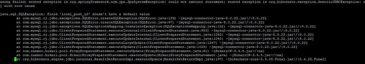
*주의 :하이버네이트를 무조건 믿어선 안된다!Mysql의 경우 Auto로 설정하면 당연히 Identity전략을 취할 것이라 생각하고 생략하거나, 추후 DBMS 종류 변경을 고려해 그냥 Auto로 사용하는 경우가 있는데, 버전에 따라 선택되는 전략이 달라질 수 있으므로,직접 DBMS에 맞는 전략을 지정해주도록 한다.
Mysql일 때 GenerationType.AUTO 에서의 전략 선택 알고리즘(빨간 화살표 흐름)
Hibernate 5부터 MySQL에서의 GenerationType.AUTO는 IDENTITY가 아닌 TABLE을 기본 시퀀스 전략으로 가져간다.
@Id @GeneratedValue(strategy = GenerationType.IDENTITY)
	private Long id;
- 기본 키 생성을 데이터베이스에 위임한다.
- 주로 MySQL, PostgreSQL, SQL Server, DB2에서 사용한다. (예: MySQL의 AUTO_ INCREMENT)
- IDENTITY 전략은,em.persist()로 객체를 영속화 시키는 시점에 곧바로 insert 쿼리가 DB로 전송되고, 거기서 반환받은 식별자 값을 가지고 1차 캐시에 엔티티를 등록시켜 관리한다.
JPA는 보통의 경우에, 트랜잭션이 commit 되는 시점에 쓰기 지연 저장소에 모아놓은 SQL을 한 번에 DB로 전송하며 실행한다. 이렇게 해야 어플리케이션과 DB 사이에 네트워크를 오가는 횟수가 줄어들고 성능면에서 이득을 볼 수 있기 때문이다.
하지만 IDENTITY전략은 DB에 기본키 생성을 위임하므로, Mysql의 경우 AUTO_INCREMENT를 활용하여 생성하는데,
이 때, JPA 입장에선 DB에 INSERT SQL를 실행하기 전엔 도저히AUTO_INCREMENT되는 값을알 수 없으므로, persist() 시점에 insert 쿼리가 실행되는 것이다. (영속성 컨텍스트로 엔티티를 관리하려면 1차 캐시에 Id값을 key 값으로 들고 있어야 하기 때문에)
아래 그림에서 1차 캐시의 Key, Value 값 구조와 쓰기 지연 SQL 저장소와 flush()가 트랜잭션 commit 직전에 이루어지는 순서를 보면 이해가 쉬울 것이다.
@Entity
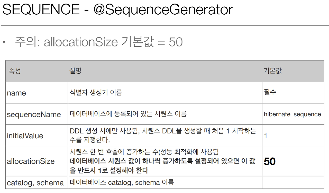
@SequenceGenerator(
name = “MEMBER_SEQ_GENERATOR",
sequenceName = “MEMBER_SEQ", //매핑할 데이터베이스 시퀀스 이름
initialValue = 1, allocationSize = 50)
public class Member {
@Id @GeneratedValue(strategy = GenerationType.SEQUENCE,
generator = "MEMBER_SEQ_GENERATOR")
private Long id;
}
- DB의 시퀀스를 활용하여 Id값을 증가시킨다.
- 데이터베이스 시퀀스는 유일한 값을 순서대로 생성하는 특별한 데이터베이스 오브젝트(예: 오라클 시퀀스)
- 오라클, PostgreSQL, DB2, H2 데이터베이스에서 사용한다.
sequenceName 으로 시퀀스를 분리하여 지정할 수 있고, allocationSize로 한 번에 사용할 시퀀스 덩어리 사이즈를 정해서 최적화 할 수 있다.
4.TABLE 전략
@Entity
@TableGenerator(
     name = "MEMBER_SEQ_GENERATOR",
     table = "MY_SEQUENCES",
     pkColumnValue = “MEMBER_SEQ", allocationSize = 1)
public class Member {
     @Id
     @GeneratedValue(strategy = GenerationType.TABLE,
     generator = "MEMBER_SEQ_GENERATOR")
     private Long id;
 }
- 키 생성 전용 테이블을 하나 만들어서 데이터베이스 시퀀스를 흉내내는 전략이다.
- 모든 데이터베이스에 적용 가능하나, 성능적인 손해가 있어서 잘 쓰지 않는다.
결론 : @GeneratedValue 사용시, 반드시 @GeneratedValue(strategy = GenerationType.전략명) 와 같은 형태로 GenerationType 명시해줘야 한다! 기본값인 AUTO는 못미덥다. 사용하지 말자!
JPA와 Mysql 사용시, @GeneratedValue의 GenerationType은 IDENTITY로 설정해서 쓰자!
java stream에서 maptoobj 함수는 중간 연산이라 되어 있습니다. 길이 n짜리 배열을 obj object n개로 채우려고 합니다. obj 클래스에는 int 자료형만 하나 있고, 우리는 이 n개의 obj가 깊은 복사가 되어야 해요. 이걸 stream을 써서 할 때, Intstream의 range 메서드와, maptoObj를 사용하면 손쉽게 처리할 수 있습니다.
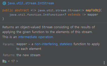
mapToObj 메서드를 봅시다. Intstream 뿐만이 아니라, Longstream과 DoubleStream에도 있습니다. 설명을 보면, 스트림으로부터 해당 함수를 적용한 객체 값들의 stream을 반환한다고 되어 있어요. 즉 입력 스트림으로부터 무언가를 받아서, 새로운 결과 가지고 있는 스트림으로 변환합니다.
n개의 크기를 가진 리스트에 깊은 복사한 Obj 오브젝트 n개를 채워야 한다고 해 볼게요. 그러면 단순하게 List를 새로 생성해서 Obj 객체를 추가해도 됩니다. 그런데, 조금 더 생각해 보면 아래와 같은 로직을 생각할 수 있습니다.
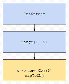
1부터 5까지 있는 stream이 있어요. 이것을 아래와 같이 변환시키면 어떨까요?
하나의 원소가 새로운 new Obj(3)으로 바뀌는 것입니다. mapToXXX류가 이러한 역할을 수행합니다. 이 경우 IntStream의 원소들을 다른 obj로 변환시키는 apply 작업을 수행했습니다.
그림으로 그리면 이런 상황인 셈입니다. 즉, mapToXXX는 스트림의 요소들을 다른 요소로 바꾼 새로운 스트림을 돌려줍니다. 위 그림에서는 x를 new Obj(3)으로 바꾸었습니다. 따라서, 1 2 3 4 5로 이루어져 있던 것을 new Obj(3), ... , new Obj(3)으로 대체하게 됩니다.
이제 문제 상황을 다시 봅시다. 저는 객체 Obj n개가 채워진 ArrayList를 원합니다. 객체 n개는 깊은 복사가 되어야 하고요. 객체 Obj는 int 필드 하나만 주어져 있습니다. n = 4라고 해 보겠습니다.
당연하게도, setter가 있기 때문에, 불변 객체가 아닙니다. 어떻게 하면 될까요? 로직부터 설계해 봅시다. 일단, 이전에 배웠던 range는 1부터 n까지의 순서를 가지는 stream을 생성합니다. 고로, IntStream.range(1, 5)를 먼저 수행합니다.
다음에, 해당 stream을 토대로 Obj로 이루어진 스트림을 새로 생성합니다. mapToObj로요.
그러면, 1부터 5까지 순서로 이루어진 Stream이 new Obj(3)으로 이루어진 4개의 객체로 이루어 집니다. 참고로 각 원소별로 apply가 별개로 동작하므로 매번 새로운 객체가 생기게 됩니다.
toList로 Stream을 List로 변환합니다.
최종 코드는 20 ~ 21번째 줄에 나와 있습니다. 23번째 줄에 list의 0번째 원소의 x 값을 2로 바꾸어 봅시다. 만약에 저 객체들이 모두 얕은 복사가 되었다면, 모두 2가 출력되었을 겁니다.
그런데 3이 출력되었습니다. 이유는 toList가 호출될 때 mapToObj에 있는 apply인 x -> new Obj(3)가 실행되기 때문입니다. 각각의 element에 대해 적용되기 때문에 별개의 새로운 오브젝트 Obj가 생성됩니다.