728x90

This article talks about the Data Encryption Standard (DES), a historic encryption algorithm known for its 56-bit key length. We explore its operation, key transformation, and encryption process, shedding light on its role in data security and its vulnerabilities in today’s context.

What is DES?

Data Encryption Standard (DES) is a block cipher with a 56-bit key length that has played a significant role in data security. Data encryption standard (DES) has been found vulnerable to very powerful attacks therefore, the popularity of DES has been found slightly on the decline. DES is a block cipher and encrypts data in blocks of size of 64 bits each, which means 64 bits of plain text go as the input to DES, which produces 64 bits of ciphertext. The same algorithm and key are used for encryption and decryption, with minor differences. The key length is 56 bits

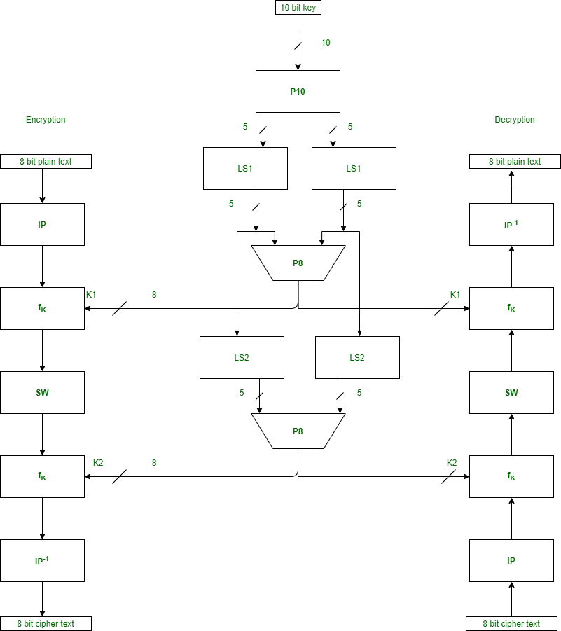
The basic idea is shown below:

We have mentioned that DES uses a 56-bit key. Actually, The initial key consists of 64 bits. However, before the DES process even starts, every 8th bit of the key is discarded to produce a 56-bit key. That is bit positions 8, 16, 24, 32, 40, 48, 56, and 64 are discarded. 


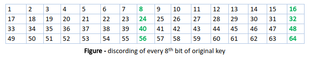
Thus, the discarding of every 8th bit of the key produces a 56-bit key from the original 64-bit key.
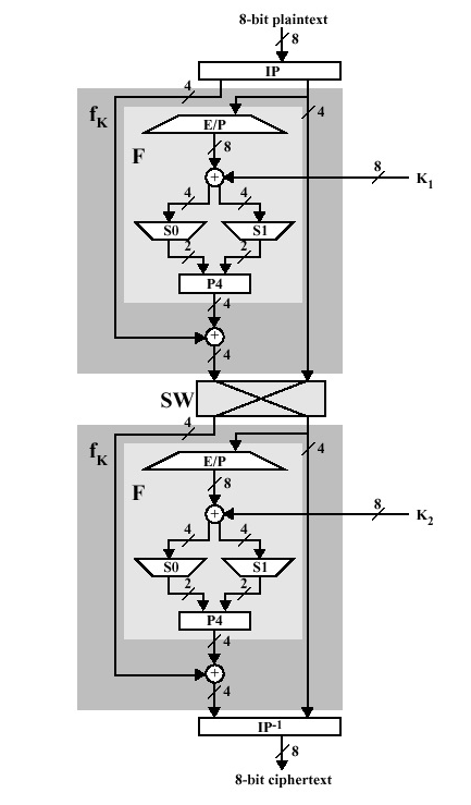
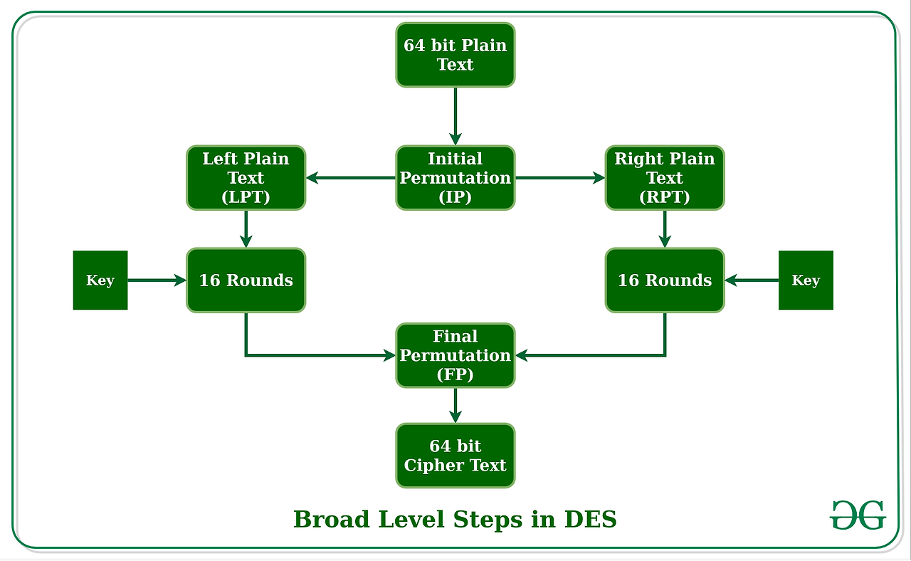
DES is based on the two fundamental attributes of cryptography: substitution (also called confusion) and transposition (also called diffusion). DES consists of 16 steps, each of which is called a round. Each round performs the steps of substitution and transposition. Let us now discuss the broad-level steps in DES. 

  • In the first step, the 64-bit plain text block is handed over to an initial Permutation (IP) function.
  • The initial permutation is performed on plain text.
  • Next, the initial permutation (IP) produces two halves of the permuted block; saying Left Plain Text (LPT) and Right Plain Text (RPT).
  • Now each LPT and RPT go through 16 rounds of the encryption process.
  • In the end, LPT and RPT are rejoined and a Final Permutation (FP) is performed on the combined block
  • The result of this process produces 64-bit ciphertext.


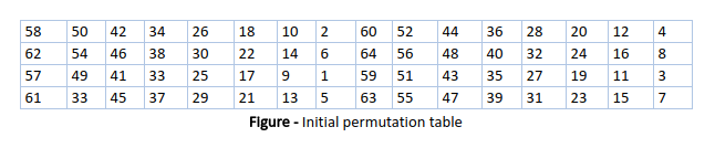
Initial Permutation (IP)

As we have noted, the initial permutation (IP) happens only once and it happens before the first round. It suggests how the transposition in IP should proceed, as shown in the figure. For example, it says that the IP replaces the first bit of the original plain text block with the 58th bit of the original plain text, the second bit with the 50th bit of the original plain text block, and so on.

This is nothing but  jugglery of bit positions of the original plain text block. the same rule applies to all the other bit positions shown in the figure.


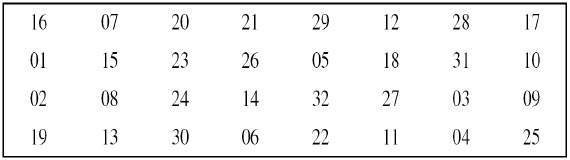
As we have noted after IP is done, the resulting 64-bit permuted text block is divided into two half blocks. Each half-block consists of 32 bits, and each of the 16 rounds, in turn, consists of the broad-level steps outlined in the figure. 


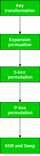
Step 1: Key transformation

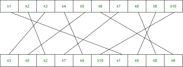
We have noted initial 64-bit key is transformed into a 56-bit key by discarding every 8th bit of the initial key. Thus, for each a 56-bit key is available. From this 56-bit key, a different 48-bit Sub Key is generated during each round using a process called key transformation. For this, the 56-bit key is divided into two halves, each of 28 bits. These halves are circularly shifted left by one or two positions, depending on the round.

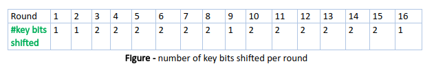
For example: if the round numbers 1, 2, 9, or 16 the shift is done by only one position for other rounds, the circular shift is done by two positions. The number of key bits shifted per round is shown in the figure.


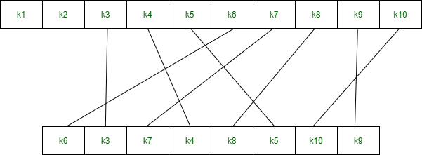
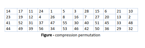
After an appropriate shift, 48 of the 56 bits are selected. From the 48 we might obtain 64 or 56 bits based on requirement which helps us to recognize that this model is very versatile and can handle any range of requirements needed or provided. for selecting 48 of the 56 bits the table is shown in the figure given below. For instance, after the shift, bit number 14 moves to the first position, bit number 17 moves to the second position, and so on. If we observe the table , we will realize that it contains only 48-bit positions. Bit number 18 is discarded (we will not find it in the table), like 7 others, to reduce a 56-bit key to a 48-bit key. Since the key transformation process involves permutation as well as a selection of a 48-bit subset of the original 56-bit key it is called Compression Permutation.

Because of this compression permutation technique, a different subset of key bits is used in each round. That makes DES not easy to crack.

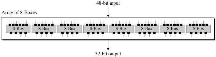
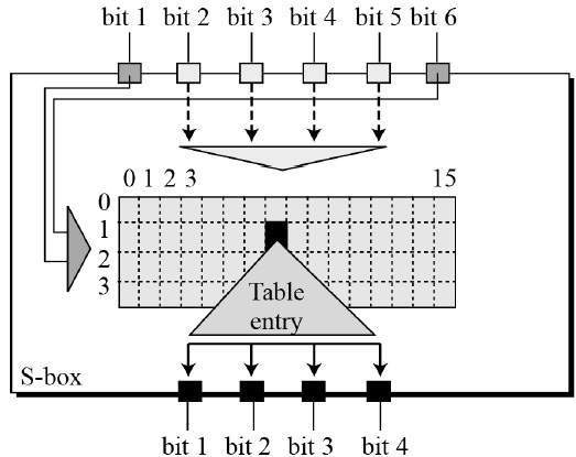
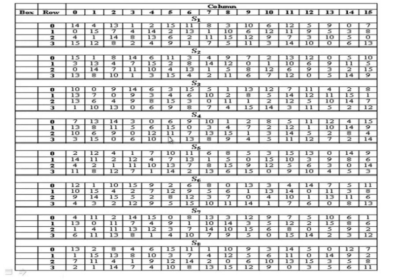
Step 2: Expansion Permutation

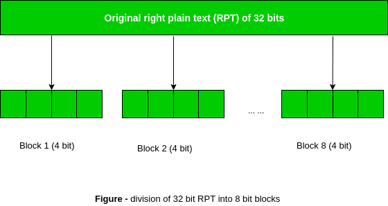
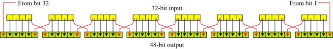
Recall that after the initial permutation, we had two 32-bit plain text areas called Left Plain Text(LPT) and Right Plain Text(RPT). During the expansion permutation, the RPT is expanded from 32 bits to 48 bits. Bits are permuted as well hence called expansion permutation. This happens as the 32-bit RPT is divided into 8 blocks, with each block consisting of 4 bits. Then, each 4-bit block of the previous step is then expanded to a corresponding 6-bit block, i.e., per 4-bit block, 2 more bits are added. 


This process results in expansion as well as a permutation of the input bit while creating output. The key transformation process compresses the 56-bit key to 48 bits. Then the expansion permutation process expands the 32-bit RPT to 48-bits. Now the 48-bit key is XOR with 48-bit RPT and the resulting output is given to the next step, which is the S-Box substitution.
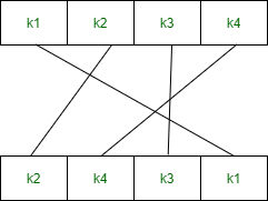


Key Generation

The round-key generator creates sixteen 48-bit keys out of a 56-bit cipher key. The process of key generation is depicted in the following illustration −

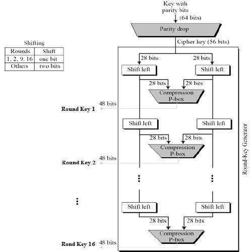
The logic for Parity drop, shifting, and Compression P-box is given in the DES description.

'Cryptography' 카테고리의 다른 글

Meet-in-the-middle attack  (0) 2024.02.29
Block Cipher modes of Operation  (31) 2024.02.29
Block Cipher Design Principles  (0) 2024.02.29
Simplified Data Encryption Standard | Set 2  (0) 2024.02.28
Simplified Data Encryption Standard Key Generation  (63) 2024.02.28
728x90

Prerequisite –

Simplified Data Encryption Standard is a simple version of Data Encryption Standard having a 10-bit key and 8-bit plain text. It is much smaller than the DES algorithm as it takes only 8-bit plain text whereas DES takes 64-bit plain text. It was developed for educational purpose so that understanding DES can become easy. It is a block cipher algorithm and uses a symmetric key for its algorithm i.e. they use the same key for both encryption and decryption. It has 2 rounds for encryption which use two different keys.

First, we need to generate 2 keys before encryption. After generating keys we pass them to each individual round for s-des encryption. The below diagram shows the steps involved in the s-des algorithm.


Components :

S-DES encryption involves four functions –

1. Initial permutation(IP) –


2. Complex function (fk) –

It is the combination of permutation and substitution functions. The below image represents a round of encryption and decryption. This round is repeated twice in each encryption and decryption.

Components in fk are –

a. Expanded Permutation (EP) –

It takes a 4-bit input and converts it into an 8-bit output.


b. S-boxes (S0 and S1) –

It is a basic component of a symmetric key algorithm that performs substitution.


c. Permutation P4 –


3. Switch (SW) –

4. Inverse of Initial Permutation (IP-1) –

First, we need to generate 2 keys before encryption.

Consider, the entered 10-bit key is - 1 0 1 0 0 0 0 0 1 0

Therefore,

Key-1 is - 1 0 1 0 0 1 0 0
Key-2 is - 0 1 0 0 0 0 1 1

Encryption –

Entered 8-bit plaintext is - 1 0 0 1 0 1 1 1

Step-1:

We perform initial permutation on our 8-bit plain text using the IP table. The initial permutation is defined as –

IP(k1, k2, k3, k4, k5, k6, k7, k8) = (k2, k6, k3, k1, k4, k8, k5, k7)
After ip = 0 1 0 1 1 1 0 1

Step-2:

After the initial permutation, we get an 8-bit block of text which we divide into 2 halves of 4 bit each.

l = 0 1 0 1  and r = 1 1 0 1

On the right half, we perform expanded permutation using EP table which converts 4 bits into 8 bits. Expand permutation is defined as –

EP(k1, k2, k3, k4) = (k4, k1, k2, k3, k2, k3, k4, k1)
After ep = 1 1 1 0 1 0 1 1

We perform XOR operation using the first key K1 with the output of expanded permutation.

Key-1 is - 1 0 1 0 0 1 0 0
(1 0 1 0 0 1 0 0) XOR (1 1 1 0 1 0 1 1) =  0 1 0 0 1 1 1 1
After XOR operation with 1st Key = 0 1 0 0 1 1 1 1

Again we divide the output of XOR into 2 halves of 4 bit each.

l = 0 1 0 0  and r = 1 1 1 1

We take the first and fourth bit as row and the second and third bit as a column for our S boxes.

S0 = [1,0,3,2
      3,2,1,0
      0,2,1,3
      3,1,3,2]

S1=  [0,1,2,3
      2,0,1,3
      3,0,1,0
      2,1,0,3]

For l = 0 1 0 0
row = 00 = 0, column = 10 = 2
S0 = 3 = 11

For r = 1 1 1 1
row = 11 = 3, column = 11 = 3
S1 = 3 = 11

After first S-Boxes combining S0 and S1 = 1 1 1 1

S boxes gives a 2-bit output which we combine to get 4 bits and then perform permutation using the P4 table. P4 is defined as –

P4(k1, k2, k3, k4) = (k2, k4, k3, k1)
After P4 = 1 1 1 1

We XOR the output of the P4 table with the left half of the initial permutation table i.e. IP table.

(0 1 0 1) XOR (1 1 1 1) = 1 0 1 0
After XOR operation with left nibble of after ip = 1 0 1 0

We combine both halves i.e. right half of initial permutation and output of ip.

Combine 1 1 0 1 and 1 0 1 0
After combine = 1 0 1 0 1 1 0 1

Step-3:

Now, divide the output into two halves of 4 bit each. Combine them again, but now the left part should become right and the right part should become left.

After step 3 = 1 1 0 1 1 0 1 0

Step-4:

Again perform step 2, but this time while doing XOR operation after expanded permutation use key 2 instead of key 1.


* 4 1 2 3 2 3 4 1 pointed EP Sequence

Expand permutation is defined as - 4 1 2 3 2 3 4 1
After second ep = 0 1 0 1 0 1 0 1
After XOR operation with 2nd Key = 0 0 0 1 0 1 1 0
After second S-Boxes = 1 1 1 1

P4 is defined as - 2 4 3 1
After P4 = 1 1 1 1

After XOR operation with left nibble of after first part = 0 0 1 0
After second part = 0 0 1 0 1 0 1 0

l = 1 1 0 1  and r = 1 0 1 0


On the right half, we perform expanded permutation using EP table which converts 4 bits into 8 bits. Expand permutation is defined as –

EP(k1, k2, k3, k4) = (k4, k1, k2, k3, k2, k3, k4, k1)
After second ep = 0 1 0 1 0 1 0 1

We perform XOR operation using second key K2 with the output of expanded permutation.

Key-2 is - 0 1 0 0 0 0 1 1
(0 1 0 0 0 0 1 1) XOR (0 1 0 1 0 1 0 1) =  0 0 0 1 0 1 1 0
After XOR operation with 2nd Key = 0 0 0 1 0 1 1 0

Again we divide the output of XOR into 2 halves of 4 bit each.

l = 0 0 0 1  and r = 0 1 1 0

We take the first and fourth bit as row and the second and third bit as a column for our S boxes.

S0 = [1,0,3,2
      3,2,1,0
      0,2,1,3
      3,1,3,2]

S1 = [0,1,2,3
      2,0,1,3
      3,0,1,0
      2,1,0,3]

For l = 0 0 0 1
row = 01 = 1 , column = 00 = 0
S0 = 3 = 11

For r = 0 1 1 0
row = 00 = 0 , column = 11 = 3
S1 = 3 = 11

After first S-Boxes combining S0 and S1 = 1 1 1 1

S boxes gives a 2-bit output which we combine to get 4 bits and then perform permutation using the P4 table. P4 is defined as –

P4(k1, k2, k3, k4) = (k2, k4, k3, k1)
After P4 = 1 1 1 1

We XOR the output of the P4 table with the left half of the initial permutation table i.e. IP table.

(1 1 0 1) XOR (1 1 1 1) = 0 0 1 0
After XOR operation with left nibble of after first part = 0 0 1 0

We combine both halves i.e. right half of initial permutation and output of ip.

Combine 1 0 1 0 and 0 0 1 0
After combine = 0 0 1 0 1 0 1 0
After second part = 0 0 1 0 1 0 1 0

Step-5:

Perform inverse initial permutation. The output of this table is the cipher text of 8 bit.

Output of step 4 : 0 0 1 0 1 0 1 0

Inverse Initial permutation is defined as –

IP-1(k1, k2, k3, k4, k5, k6, k7, k8) = (k4, k1, k3, k5, k7, k2, k8, k6)

8-bit Cipher Text will be = 0 0 1 1 1 0 0 0

'Cryptography' 카테고리의 다른 글

Meet-in-the-middle attack  (0) 2024.02.29
Block Cipher modes of Operation  (31) 2024.02.29
Block Cipher Design Principles  (0) 2024.02.29
DES (Data Encryption Standard)  (0) 2024.02.28
Simplified Data Encryption Standard Key Generation  (63) 2024.02.28
728x90

Simplified Data Encryption Standard (S-DES) is a simple version of the DES Algorithm. It is similar to the DES algorithm but is a smaller algorithm and has fewer parameters than DES. It was made for educational purposes so that understanding DES would become simpler.  It is a block cipher that takes a block of plain text and converts it into ciphertext.  It takes a block of 8 bit.

It is a symmetric key cipher i.e. they use the same key for both encryption and decryption. In this article, we are going to demonstrate key generation for s-des encryption and decryption algorithm. We take a random 10-bit key and produce two 8-bit keys which will be used for encryption and decryption.

Key Generation Concept: In the key generation algorithm, we accept the 10-bit key and convert it into two 8 bit keys. This key is shared between both sender and receiver. 


In the key generation, we use three functions:


1. Permutation P10


2. Permutation P8


3. Left Shift


Step 1: We accepted a 10-bit key and permuted the bits by putting them in the P10 table.

Key = 1 0 1 0 0 0 0 0 1 0
(k1, k2, k3, k4, k5, k6, k7, k8, k9, k10) = (1, 0, 1, 0, 0, 0, 0, 0, 1, 0)

P10 Permutation is: P10(k1, k2, k3, k4, k5, k6, k7, k8, k9, k10) = (k3, k5, k2, k7, k4, k10, k1, k9, k8, k6) 
After P10, we get 1 0 0 0 0 0 1 1 0 0


Step 2: We divide the key into 2 halves of 5-bit each.

l=1 0 0 0 0, r=0 1 1 0 0

Step 3: Now we apply one bit left-shift on each key.

l = 0 0 0 0 1, r = 1 1 0 0 0


Step 4: Combine both keys after step 3 and permute the bits by putting them in the P8 table. The output of the given table is the first key K1.

After LS-1 combined, we get 0 0 0 0 1 1 1 0 0 0
P8 permutation is: P8(k1, k2, k3, k4, k5, k6, k7, k8, k9, k10) = (k6, k3, k7, k4, k8, k5, k10, k9)
After P8, we get Key-1 : 1 0 1 0 0 1 0 0

Step 5: The output obtained from step 3 i.e. 2 halves after one bit left shift should again undergo the process of two-bit left shift.

Step 3 output - l = 0 0 0 0 1, r = 1 1 0 0 0 
After two bit shift - l = 0 0 1 0 0, r = 0 0 0 1 1

Step 6: Combine the 2 halves obtained from step 5 and permute them by putting them in the P8 table. The output of the given table is the second key K2.

After LS-2 combined = 0 0 1 0 0 0 0 0 1 1
P8 permutation is: P8(k1, k2, k3, k4, k5, k6, k7, k8, k9, k10) = (k6, k3, k7, k4, k8, k5, k10, k9)
After P8, we get Key-2 : 0 1 0 0 0 0 1 1

Final Output:

Key-1 is: 1 0 1 0 0 1 0 0
Key-2 is: 0 1 0 0 0 0 1 1


회사에서 Cryptography 관련된 자료를 다시 공부하라고 넘겨주셧는데 자료가 굉장히 불친절하게 되어 있었다. 정확하게는 왜때문에 어떤 과정이 나오는지에 대한 부분이 잘 안나와 있기 때문이었다.


Simple DES 라서 사실상 쓰이는 일은 없겠지만 (물론 있을 수도 있고), 오랜만에 봐서 빡쳐가지고 찾아보고 가져왔다.


이건 Key Generation 을 하는 딱 1부 파트이기 때문에, 실제 Cipher Suite 인 Cipher 는 다음 글에

'Cryptography' 카테고리의 다른 글

Meet-in-the-middle attack  (0) 2024.02.29
Block Cipher modes of Operation  (31) 2024.02.29
Block Cipher Design Principles  (0) 2024.02.29
DES (Data Encryption Standard)  (0) 2024.02.28
Simplified Data Encryption Standard | Set 2  (0) 2024.02.28
728x90

Continuous integration (CI) and continuous delivery (CD), also known as CI/CD, embodies a culture and set of operating principles and practices that application development teams use to deliver code changes both more frequently and more reliably.

CI/CD is a best practice for devops teams. It is also a best practice in agile methodology. By automating code integration and delivery, CI/CD lets software development teams focus on meeting business requirements while ensuring that software is high in quality and secure.

CI/CD defined

Continuous integration is a coding philosophy and set of practices that drive development teams to frequently implement small code changes and check them in to a version control repository. Most modern applications require developing code using a variety of platforms and tools, so teams need a consistent mechanism to integrate and validate changes. Continuous integration establishes an automated way to build, package, and test their applications. Having a consistent integration process encourages developers to commit code changes more frequently, which leads to better collaboration and code quality.

Continuous delivery picks up where continuous integration ends, and automates application delivery to selected environments, including production, development, and testing environments. Continuous delivery is an automated way to push code changes to these environments.

Automating the CI/CD pipeline

CI/CD tools help store the environment-specific parameters that must be packaged with each delivery. CI/CD automation then makes any necessary service calls to web servers, databases, and other services that need restarting. It can also execute other procedures following deployment.

Because the objective is to deliver quality code and applications, CI/CD also requires continuous testing. In continuous testing, a set of automated regression, performance, and other tests are executed in the CI/CD pipeline.

A mature devops team with a robust CI/CD pipeline can also implement continuous deployment, where application changes run through the CI/CD pipeline and passing builds are deployed directly to the production environment. Some teams practicing continuous deployment elect to deploy daily or even hourly to production, though continuous deployment isn’t optimal for every business application.

Organizations that implement a CI/CD pipeline often have several devops best practices in place, including microservices development, serverless architecture, continuous testing, infrastructure as code, and deployment containers. Each of these practices improves process automation and increases the robustness of cloud computing environments. Together, these practices provide a strong foundation to support continuous deployment.

How continuous integration improves collaboration and code quality

Continuous integration is a development philosophy backed by process mechanics and automation. When practicing continuous integration, developers commit their code into the version control repository frequently; most teams have a standard of committing code at least daily. The rationale is that it’s easier to identify defects and other software quality issues on smaller code differentials than on larger ones developed over an extensive period. In addition, when developers work on shorter commit cycles, it is less likely that multiple developers will edit the same code and require a merge when committing.

Teams implementing continuous integration often start with the version control configuration and practice definitions. Although checking in code is done frequently, agile teams develop features and fixes on shorter and longer timeframes. Development teams practicing continuous integration use different techniques to control what features and code are ready for production.

Many teams use feature flags, a configuration mechanism to turn features and code on or off at runtime. Features that are still under development are wrapped with feature flags in the code, deployed with the main branch to production, and turned off until they are ready to be used. In recent research, devops teams using feature flags had a ninefold increase in development frequency. Feature flagging tools such as CloudBees, Optimizely Rollouts, and LaunchDarkly integrate with CI/CD tools to support feature-level configurations.

Automated builds

In an automated build process, all the software, database, and other components are packaged together. For example, if you were developing a Java application, continuous integration would package all the static web server files such as HTML, CSS, and JavaScript along with the Java application and any database scripts.

Continuous integration not only packages all the software and database components, but the automation will also execute unit tests and other types of tests. Testing provides vital feedback to developers that their code changes didn’t break anything.

Most CI/CD tools let developers kick off builds on demand, triggered by code commits in the version control repository, or on a defined schedule. Teams need to determine the build schedule that works best for the size of the team, the number of daily commits expected, and other application considerations. A best practice is to ensure that commits and builds are fast; otherwise, these processes may impede teams trying to code quickly and commit frequently.

Continuous testing and security automation

Automated testing frameworks help quality assurance engineers define, execute, and automate various types of tests that can help development teams know whether a software build passes or fails. They include functionality tests developed at the end of every sprint and aggregated into a regression test for the entire application. The regression test informs the team whether a code change failed one or more of the tests developed across the functional areas of the application where there is test coverage.

A best practice is to enable and require developers to run all or a subset of regression tests in their local environments. This step ensures developers only commit code to version control after code changes have passed regression tests.

Regression tests are just the beginning, however. Devops teams also automate performance, API, browser, and device testing. Today, teams can also embed static code analysis and security testing in the CI/CD pipeline for shift-left testing. Agile teams can also test interactions with third-party APIs, SaaS, and other systems outside of their control using service virtualization. The key is being able to trigger these tests through the command line, a webhook, or a web service, and get a success or failure response.

Continuous testing implies that the CI/CD pipeline integrates test automation. Some unit and functionality tests will flag issues before or during the continuous integration process. Tests that require a full delivery environment, such as performance and security testing, are often integrated into continuous delivery and done after a build is delivered to its target environments.

Stages in the continuous delivery pipeline

Continuous delivery is the automation that pushes applications to one or more delivery environments. Development teams typically have several environments to stage application changes for testing and review. A devops engineer uses a CI/CD tool such as Jenkins, CircleCI, AWS CodeBuild, Azure DevOps, Atlassian Bamboo, Argo CD, Buddy, Drone, or Travis CI to automate the steps and provide reporting.

For example, Jenkins users define their pipelines in a Jenkinsfile that describes different stages such as build, test, and deploy. Environment variables, options, secret keys, certifications, and other parameters are declared in the file and then referenced in stages. The post section handles error conditions and notifications.

A typical continuous delivery pipeline has build, test, and deploy stages. The following activities could be included at different stages:

  • Pulling code from version control and executing a build.
  • Enabling stage gates for automated security, quality, and compliance checks and supporting approvals when required.
  • Executing any required infrastructure steps automated as code to stand up or tear down cloud infrastructure.
  • Moving code to the target computing environment.
  • Managing environment variables and configuring them for the target environment.
  • Pushing application components to their appropriate services, such as web servers, APIs, and database services.
  • Executing any steps required to restart services or call service endpoints needed for new code pushes.
  • Executing continuous tests and rollback environments if tests fail.
  • Providing log data and alerts on the state of the delivery.
  • Updating configuration management databases and sending alerts to IT service management workflows on completed deployments.

A more sophisticated continuous delivery pipeline might have additional steps such as synchronizing data, archiving information resources, or patching applications and libraries.

Teams using continuous deployment to deliver to production may use different cutover practices to minimize downtime and manage deployment risks. One option is configuring canary deployments with an orchestrated shift of traffic usage from the older software version to the newer one. 

CI/CD tools and plugins

CI/CD tools typically support a marketplace of plugins. For example, Jenkins lists more than 1,800 plugins that support integration with third-party platforms, user interface, administration, source code management, and build management.

Once the development team has selected a CI/CD tool, it must ensure that all environment variables are configured outside the application. CI/CD tools allow development teams to set these variables, mask variables such as passwords and account keys, and configure them at the time of deployment for the target environment.

Continuous delivery tools also provide dashboard and reporting functions, which are enhanced when devops teams implement observable CI/CD pipelines. Developers are alerted if a build or delivery fails. The dashboard and reporting functions integrate with version control and agile tools to help developers determine what code changes and user stories made up the build.

Measuring CI/CD success with devops KPIs

The impact of implementing CI/CD pipelines can be measured as a devops key performance indicator (KPI). Indicators such as deployment frequency, change lead time, and incident meantime to recovery (MTTR) are often improved by implementing CI/CD with continuous testing. However, CI/CD is just one process that can drive these improvements, and there are other prerequisites to improving deployment frequencies.

CI/CD with Kubernetes and serverless architectures

Many teams operating CI/CD pipelines in cloud environments also use containers such as Docker and orchestration systems such as Kubernetes. Containers allow for packaging and shipping applications in a standard, portable way. Containers make it easy to scale up or tear down environments with variable workloads.

There are many approaches to using containers, infrastructure as code (IaC), and CI/CD pipelines together. Free tutorials such as Kubernetes with Jenkins or Kubernetes with Azure DevOps can help you explore your options.

Another option is to use a serverless architecture to deploy and scale your applications. In a serverless environment, the cloud service provider manages the infrastructure, and the application consumes resources as needed based on its configuration. On AWS, for example, serverless applications run as Lambda functions and deployments can be integrated into a Jenkins CI/CD pipeline with a plugin. Azure serverless and GPS serverless computing are similar services.

Next generation CI/CD applications

You may be wondering about some of the more advanced areas for CI/CD pipeline development and management. Here are a few notable ones:

  • MLOps is the IaC and CI/CD of machine learning models and supports infrastructure, integration, and deployment to training and production environments.
  • Synthetic data generation techniques use machine learning to create data sets used by test automation engineers to test APIs and by data scientists to train models.
  • AIOps platforms, or machine learning and automation in IT Ops, aggregate observability data and correlates alerts from multiple sources into incidents. Automations can trigger CI/CD deployments and rollbacks as required.
  • Teams working on microservices create reusable pipelines to support and scale development and review options on Azure and AWS.
  • Engineers use CI/CD in other areas, including network configuration, embedded systems, database changes, IoT, and AR/VR.

Conclusion

To recap, continuous integration packages and tests software builds and alerts developers if their changes fail any unit tests. Continuous delivery is the automation that delivers applications, services, and other technology deployments to the runtime infrastructure and may execute additional tests.

Developing a CI/CD pipeline is a standard practice for businesses that frequently improve applications and require a reliable delivery process. Once in place, the CI/CD pipeline lets the team focus more on enhancing applications and less on the details of delivering it to various environments.

Getting started with CI/CD requires devops teams to collaborate on technologies, practices, and priorities. Teams need to develop consensus on the right approach for their business and technologies. Once a pipeline is in place, the team should follow CI/CD practices consistently.

+ Recent posts